Ultrasonic diagnostic apparatus and ultrasonic probe

a diagnostic apparatus and probe technology, applied in diagnostics, ultrasonic/sonic/infrasonic data transmission, medical science, etc., can solve problems such as false recognition of ultrasonic probes, defective images, and inability to connect, so as to reduce the concern about false recognition and the effect of wireless connection

Active Publication Date: 2010-07-29
FUJIFILM CORP
View PDF4 Cites 61 Cited by
  • Summary
  • Abstract
  • Description
  • Claims
  • Application Information

AI Technical Summary

Benefits of technology

[0017]According to the first aspect of the present invention, the ultrasonic probe includes the probe ID transport unit having the transport distance shorter than that of the first wireless communication unit, for transporting the probe ID for identifying the ultrasonic probe to the outside in a contact manner or a noncontact manner, and the ultrasonic diagnostic apparatus main body acquires the probe ID transported from the probe ID transport unit and receives the transfer signal from an ultrasonic probe having the acquired probe ID. Therefore, wireless connection can be reliably established between the ultrasonic probe and the ultrasonic diagnostic apparatus main body by using the first and second wireless communication units after the ultrasonic probe is reliably recognized by using the probe ID transported from the probe ID transport unit, and thus, concern about false recognition can be reduced and the ultrasonic probe and the ultrasonic diagnostic apparatus main body can be appropriately connected. Further, the same advantages can be obtained by the ultrasonic probe acquiring the main body ID for identifying the ultrasonic diagnostic apparatus main body instead of the ultrasonic diagnostic apparatus main body acquiring the probe ID for identifying the ultrasonic probe.
[0018]Furthermore, according to the second aspect of the present invention, the power supply is started when the mounting of the recording medium on the recording medium mounting unit of the ultrasonic probe is detected, and thereby, the availability of connection between the ultrasonic probe and the ultrasonic diagnostic apparatus main body can be managed without wasting the internal power supply of the ultrasonic probe.

Problems solved by technology

However, in the case where there are plural connectable ultrasonic probes and plural ultrasonic diagnostic apparatus main bodies in a range where wireless communication is enabled, an operation for setting or the like is complicated in order to reliably establish wireless communication between a specific ultrasonic probe and a specific ultrasonic diagnostic apparatus main body to be used, and there is a danger of improper connection when an error occurs in the operation.
Further, in the case where wireless communication condition is poor, false recognition of the ultrasonic probe may occur at establishment of wireless communication.
In this case, a different kind of control is made by the ultrasonic diagnostic apparatus main body and an abnormal movement may occur, and therefore, there is a possibility that a problem such as a defective image may occur.

Method used


Image

  • Ultrasonic diagnostic apparatus and ultrasonic probe
  • Ultrasonic diagnostic apparatus and ultrasonic probe
  • Ultrasonic diagnostic apparatus and ultrasonic probe

Examples


first embodiment

[0035]First, an ultrasonic diagnostic apparatus according to the present invention will be explained.

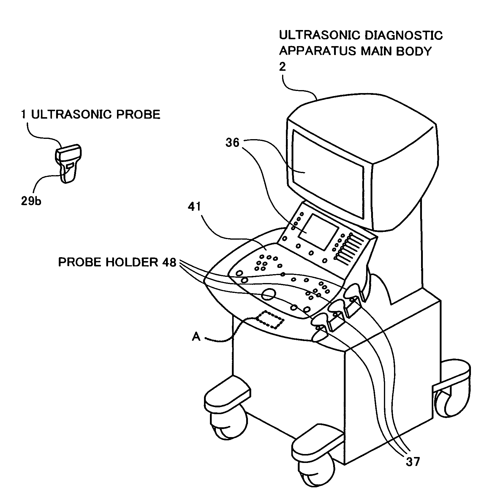
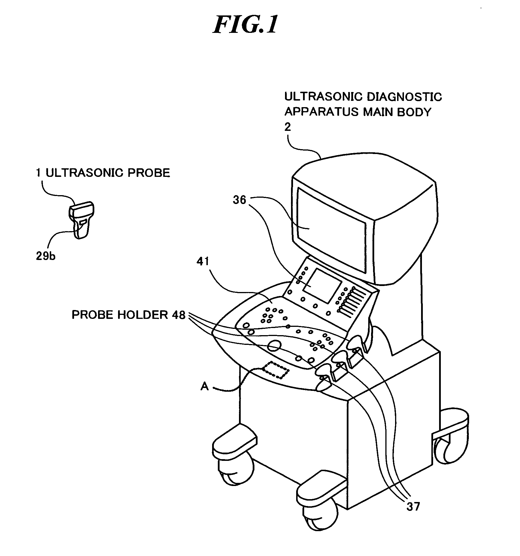
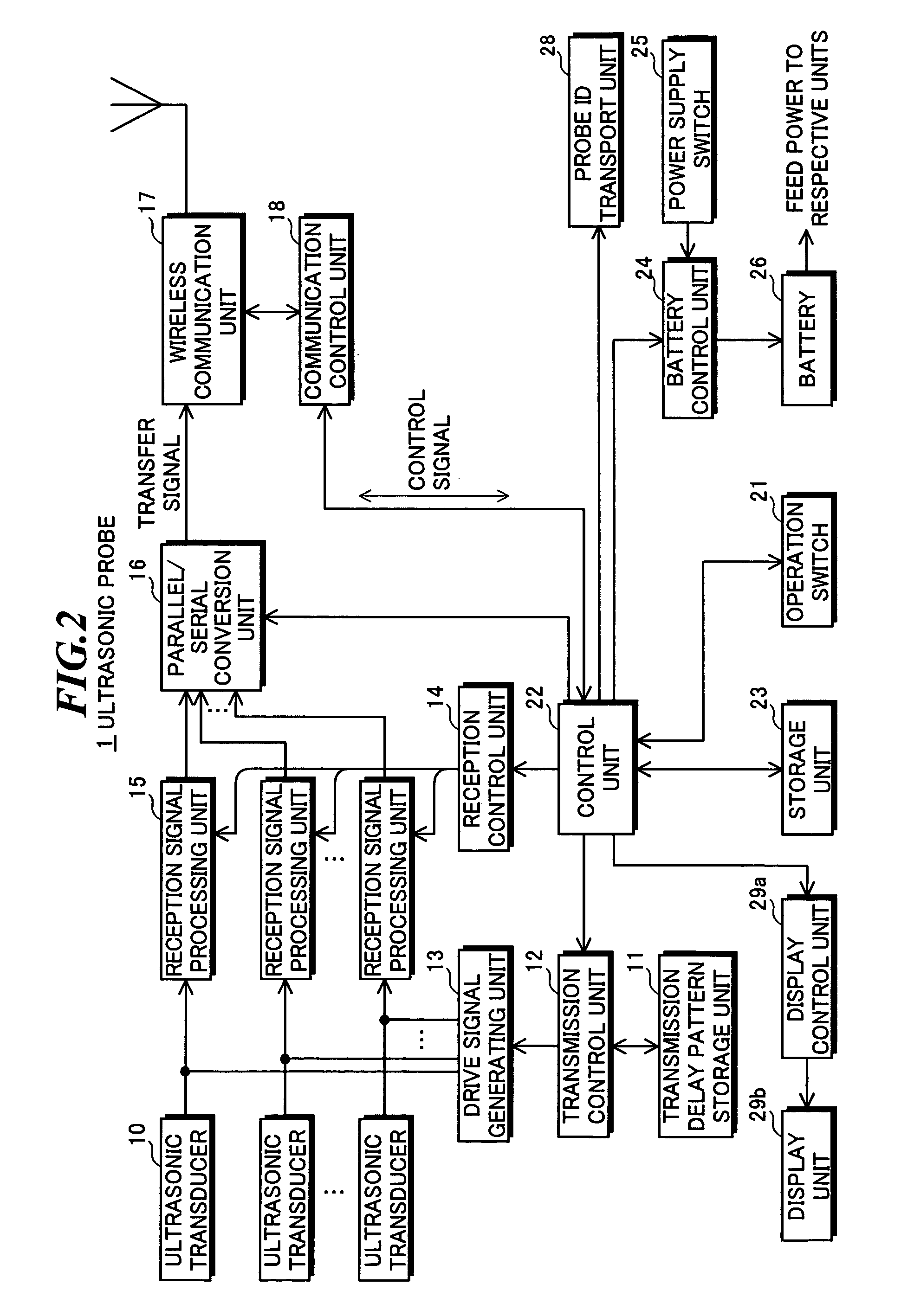
[0036]FIG. 2 is a block diagram showing a configuration of an ultrasonic probe according to the first embodiment of the present invention, and FIG. 3 is a block diagram showing a configuration of an ultrasonic diagnostic apparatus main body according to the first embodiment of the present invention. The ultrasonic probe 1 may be an external probe of linear-scan type, convex-scan type, sector-scan type, or the like, or an ultrasonic endoscopic probe of radial-scan type or the like.

[0037]As shown in FIG. 2, the ultrasonic probe 1 includes plural ultrasonic transducers10 forming a one-dimensional or two-dimensional transducer array, a transmission delay pattern storage unit 11, a transmission control unit 12, a drive signal generating unit 13, a reception control unit 14, plural channels of reception signal processing units 15, a parallel / serial conversion unit 16, a wireless communicat...

second embodiment

[0098]Next, an ultrasonic diagnostic apparatus according to the present invention will be explained.

[0099]FIG. 7 is a block diagram showing a configuration of an ultrasonic probe according to the second embodiment of the present invention, and FIG. 8 is a block diagram showing a configuration of an ultrasonic diagnostic apparatus main body according to the second embodiment of the present invention.

[0100]In the second embodiment, instead of performing authentication by using the probe ID, authentication is performed by using a main body ID unique to the ultrasonic diagnostic apparatus main body. For the purpose, a main body ID acquiring unit 30 as shown in FIG. 7 is provided in place of the probe ID transport unit 28 as shown in FIG. 2, and a main body ID transport unit 48 as shown in FIG. 8 is provided in place of the probe ID acquiring unit 47 as shown in FIG. 3.

[0101]In order to decide combination of an ultrasonic probe 1a and an ultrasonic diagnostic apparatus main body 2a prior...

third embodiment

[0115]Next, an ultrasonic diagnostic apparatus according to the present invention will be explained.

[0116]FIG. 10 is a block diagram showing a configuration of an ultrasonic probe according to the third embodiment of the present invention, and FIG. 11 is a block diagram showing a configuration of an ultrasonic diagnostic apparatus main body according to the third embodiment of the present invention. An ultrasonic diagnostic apparatus according to the third embodiment of the present invention includes an ultrasonic probe 1b as shown in FIG. 10 and an ultrasonic diagnostic apparatus main body 2b as shown in FIG. 11. The ultrasonic probe 1b may be an external probe of linear-scan type, convex-scan type, sector-scan type, or the like, or an ultrasonic endoscopic probe of radial-scan type or the like.

[0117]As shown in FIG. 10, the ultrasonic probe 1b includes plural ultrasonic transducers 10 forming a one-dimensional or two-dimensional transducer array, a transmission delay pattern stora...


PUM


Abstract

When a transfer signal according to ultrasonic echoes is wirelessly transmitted from an ultrasonic probe to an ultrasonic diagnostic apparatus main body, the main body and the probe are reliably connected without false recognition. An ultrasonic diagnostic apparatus includes an ultrasonic probe and an ultrasonic diagnostic apparatus main body, and the ultrasonic probe includes a probe ID transport unit having a transport distance shorter than that of a first wireless communication unit for transporting a probe ID for identification of itself in contact or noncontact to an outside, the ultrasonic diagnostic apparatus main body includes a probe ID acquiring unit for acquiring the probe ID transported from the probe ID transport unit, and a second wireless communication unit receives the transfer signal from the ultrasonic probe having the probe ID acquired by the probe ID acquiring unit.

Description

CROSS-REFERENCE TO RELATED APPLICATION[0001]The present application claims priority from Japanese Patent Applications No. 2009-016639 filed on Jan. 28, 2009 and No. 2009-079313 filed on Mar. 27, 2009, the contents of which are incorporated herein by reference in their entirety.BACKGROUND OF THE INVENTION[0002]1. Field of the Invention[0003]The present invention relates to an ultrasonic diagnostic apparatus in which an ultrasonic probe transmits a signal, which is obtained by transmitting and receiving ultrasonic waves and thereby imaging organs and so on within a living body, to an ultrasonic diagnostic apparatus main body via wireless communication. Further, the present invention relates to an ultrasonic probe to be used in such an ultrasonic diagnostic apparatus.[0004]2. Description of a Related Art[0005]In medical fields, various imaging technologies have been developed for observation and diagnoses within an object to be inspected. Especially, ultrasonic imaging for acquiring in...

Claims


Application Information

Patent Timeline
Patent Type & Authority Applications(United States)
IPC IPC(8): A61B8/00
CPCA61B8/00A61B8/4405A61B8/56A61B8/4472A61B8/4438A61B8/4209
Inventor SATOH, YOSHIAKIKARASAWA, HIROYUKI
Owner FUJIFILM CORP
Why Eureka
Try Eureka