Discharge arm assembly for pumping units

a technology for discharging arm and pumping unit, which is applied in the direction of water supply installation, sealing/packing, and wellbore/well accessories, etc. it can solve the problems of significant labor reduction over existing practices in the prior art, and achieve the effect of reducing clutter and eliminating undue wear in the swivel joints

Active Publication Date: 2010-08-05
FMC TECH INC
View PDF29 Cites 47 Cited by
  • Summary
  • Abstract
  • Description
  • Claims
  • Application Information

AI Technical Summary

Benefits of technology

[0007]Ideally, the discharge arm assembly comprises no more swivel joints than are required to ensure that the necessary degrees of freedom are present between the pumping unit and the collection manifold. In addition, since the articulated arm is supported by the base unit, none of the swivel joints is required to rest on the ground. This greatly reduces the clutter in the area between the pumping unit and the collection manifold and eliminates undue we...

Problems solved by technology

This, along with having to make only one connection, results in ...

Method used


Image

  • Discharge arm assembly for pumping units
  • Discharge arm assembly for pumping units
  • Discharge arm assembly for pumping units

Examples


Embodiment Construction

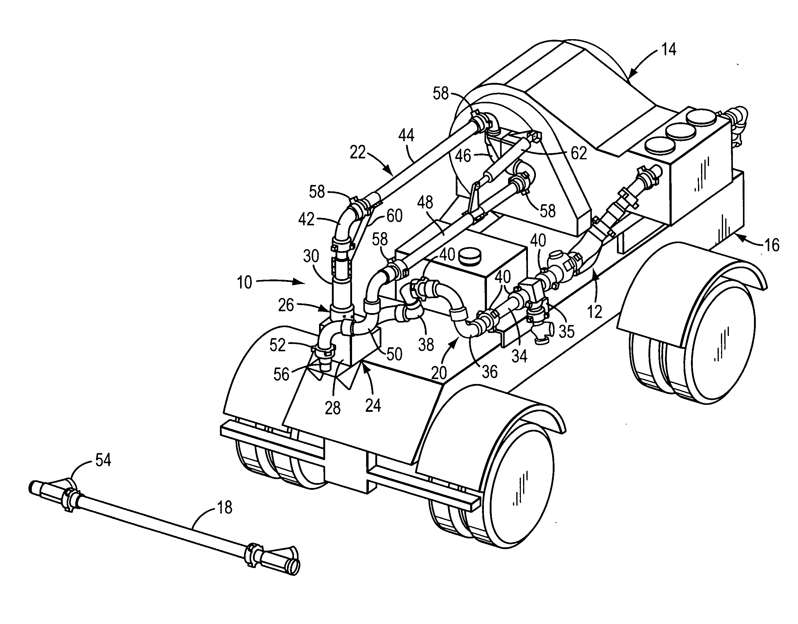
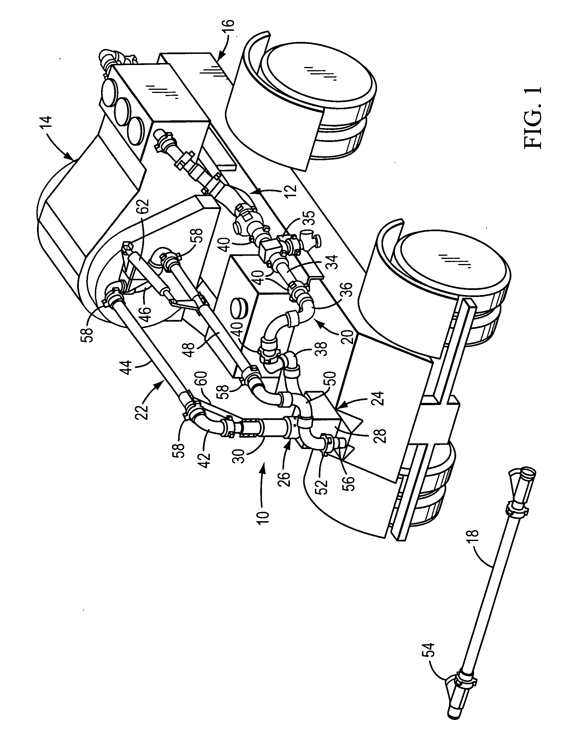
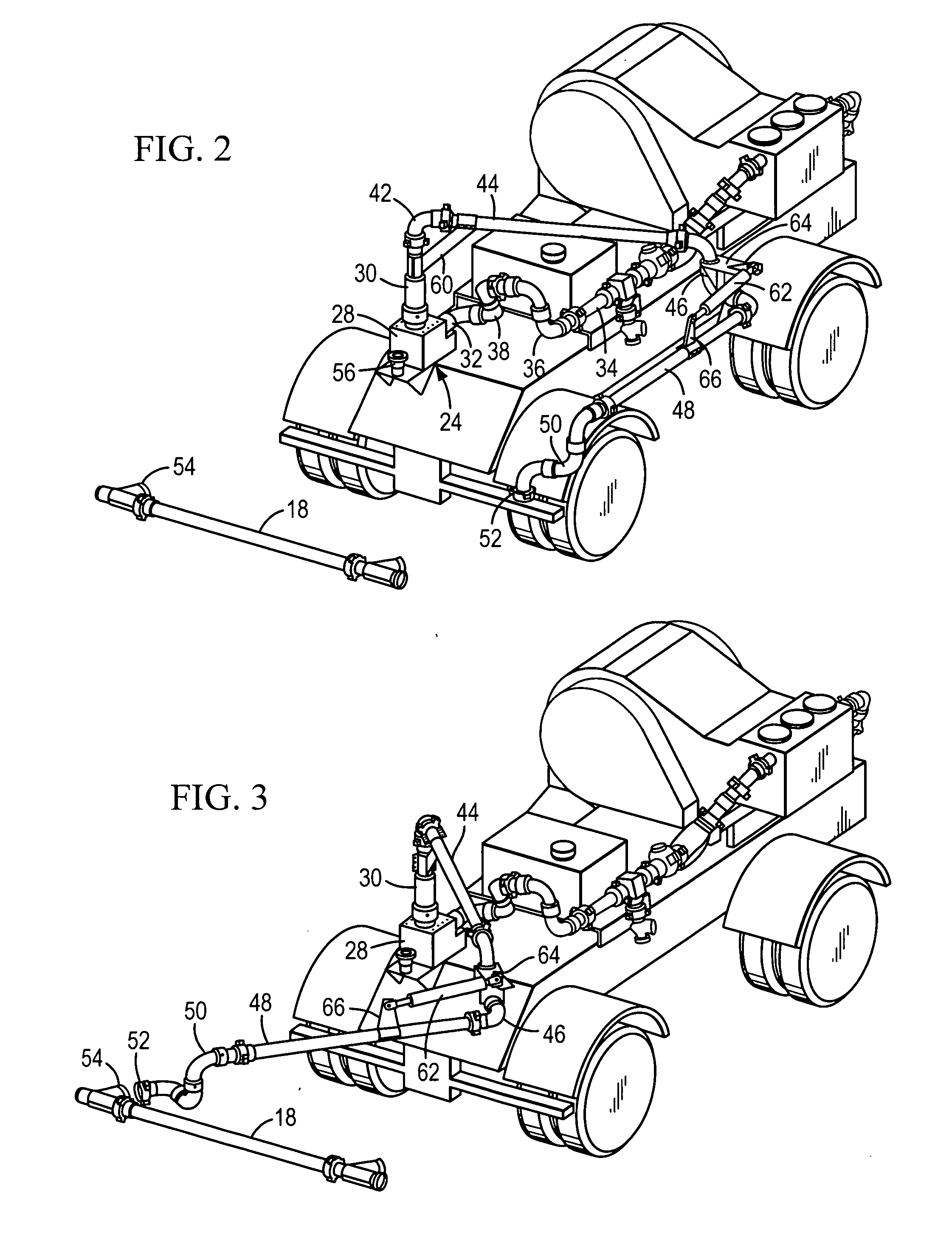
[0013]Referring to FIGS. 1 through 3, the discharge arm assembly of the present invention, which is indicated generally by reference number 10, is shown connected to the discharge pipe assembly 12 of a well service pumping unit 14 that is mounted on a trailer 16. The trailer 16 is shown parked in the vicinity of a collection manifold 18 which is connected to a well (not shown). The discharge arm assembly 10 is used to connect the pump discharge pipe assembly 12 to the collection manifold 18 during well service operations.

[0014]The discharge arm assembly 10, which in FIG. 1 is shown in its stowed position on the trailer 16, includes a jumper line 20 which is connected to an articulated arm 22 via a base unit 24. The base unit 24 comprises a base conduit 26 which is rigidly secured to the trailer 16 and which provides for fluid communication between the jumper line 20 and the articulated arm 22. In the exemplary embodiment of the invention shown in FIG. 1, the base conduit 26 comprise...


PUM


Abstract

A discharge arm assembly for a truck or trailer-mounted pumping unit comprises a jumper line which is connected to the outlet of the pumping unit, a base unit which is connected to the outlet of the jumper line, and an articulated arm which is connected to the outlet of the base unit. The base unit includes a base conduit which is rigidly secured to the truck or trailer and a swivel arm which is rotatable about a generally vertical axis. The articulated arm comprises a first generally straight pipe which is connected to the swivel arm by a generally 90° elbow. A brace member comprises a first end which is connected to the swivel arm and a second end which is connected to the first pipe to thereby support the first pipe for movement in a generally horizontal plane.

Description

[0001]The present application is based on and claims priority from U.S. Provisional Patent Application No. 61 / 201,609, which was filed on Dec. 11, 2008.BACKGROUND OF THE INVENTION[0002]The present invention is directed to a discharge pipe assembly for truck and trailer mounted high pressure well service pumping units. More specifically, the invention is directed to a discharge arm assembly comprising an articulated arm which is mounted to the truck or trailer bed and is connected to a fixed jumper line that in turn is connected to the pumping unit.[0003]High pressure well service pumping units are commonly used in the hydrocarbon production industry to inject a variety of fluids into an oil or gas well during certain well servicing operations. For example, during a fracturing operation such pumping units are used to inject a particle-containing slurry into the well in order to fracture the hydrocarbon bearing formation and thereby produce channels within the formation through which ...

Claims


Application Information

Patent Timeline
IPC IPC(8): E03B1/00
CPCE21B33/13Y10T137/6881Y10T137/8807
Inventor GARNER, WILLIAM H.KILLINGSWORTH, ALAN R.OSKINS, DAVID M.CRAWFORD, PAUL A.UNGCHUSRI, TEP
Owner FMC TECH INC
Why Eureka
Try Eureka