Methods, systems, and tool assemblies for distributing weight between an earth-boring rotary drill bit and a reamer device

a technology of earth-boring rotary drill bit and reamer device, which is applied in the direction of drilling rods, drilling pipes, cutting machines, etc., can solve the problems of inability to achieve uniform distribution of weight-on-bit applied to the bottom hole assembly, relative hard and difficult drilling through, and limited penetration rate of the bottom hole assembly

Active Publication Date: 2010-08-05
BAKER HUGHES INC
View PDF60 Cites 30 Cited by
  • Summary
  • Abstract
  • Description
  • Claims
  • Application Information

AI Technical Summary

Problems solved by technology

For example, some formations are relatively soft and are easily drilled through, while others are relatively hard and difficult to drill through.
As a result, the rate of penetration of the bottom hole assembly is limited by the rate of penetration of the reamer device, and the drill bit may begin to drill out the underlying, softer formation material without advancing into the formation at a rate sufficient to maintain a consistent, desired depth of cut (DOC) by the cutting structures of the drill bit.
Consequently, the weight-on-bit appli

Method used


Image

  • Methods, systems, and tool assemblies for distributing weight between an earth-boring rotary drill bit and a reamer device
  • Methods, systems, and tool assemblies for distributing weight between an earth-boring rotary drill bit and a reamer device
  • Methods, systems, and tool assemblies for distributing weight between an earth-boring rotary drill bit and a reamer device

Examples


example

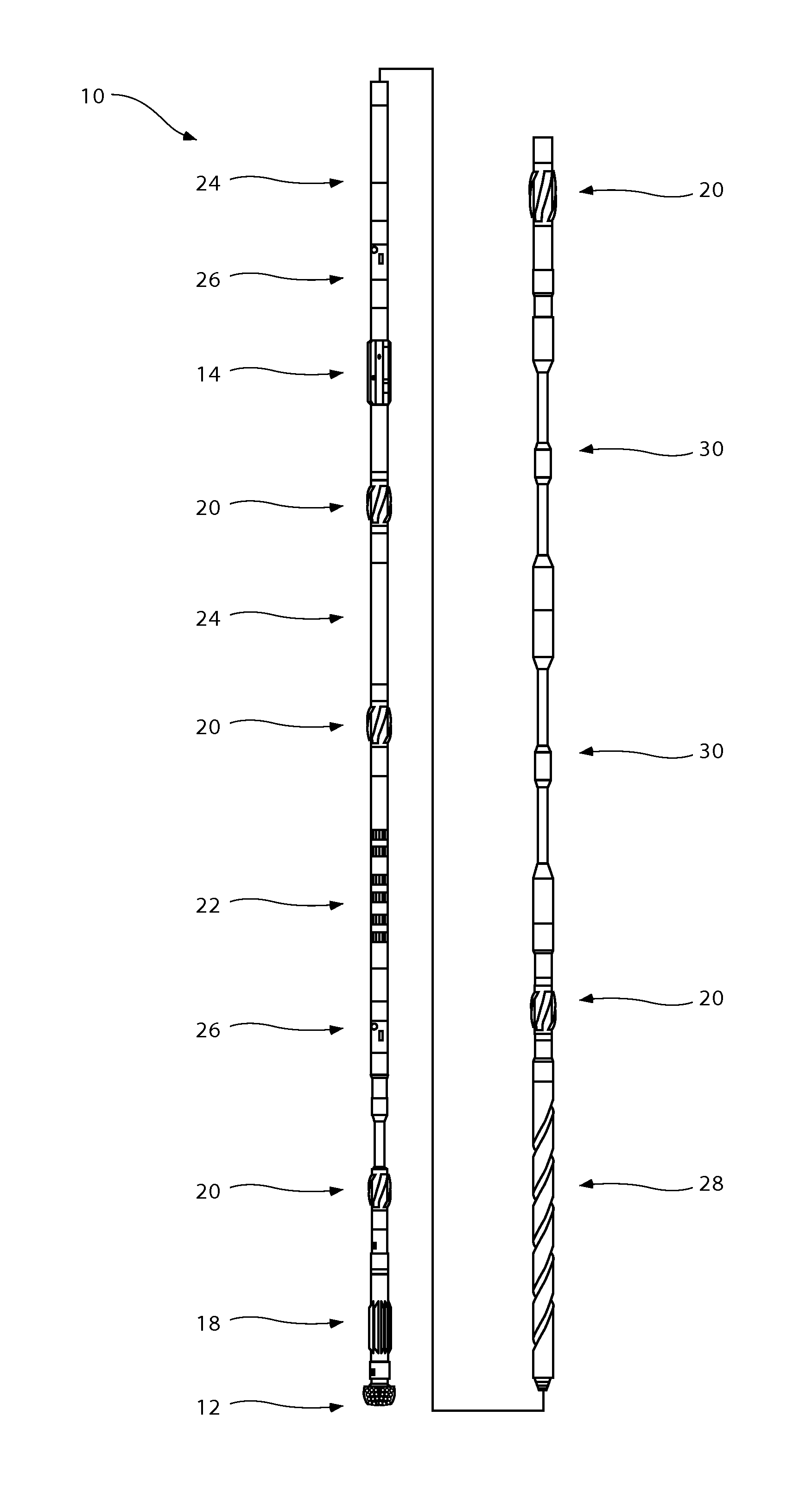
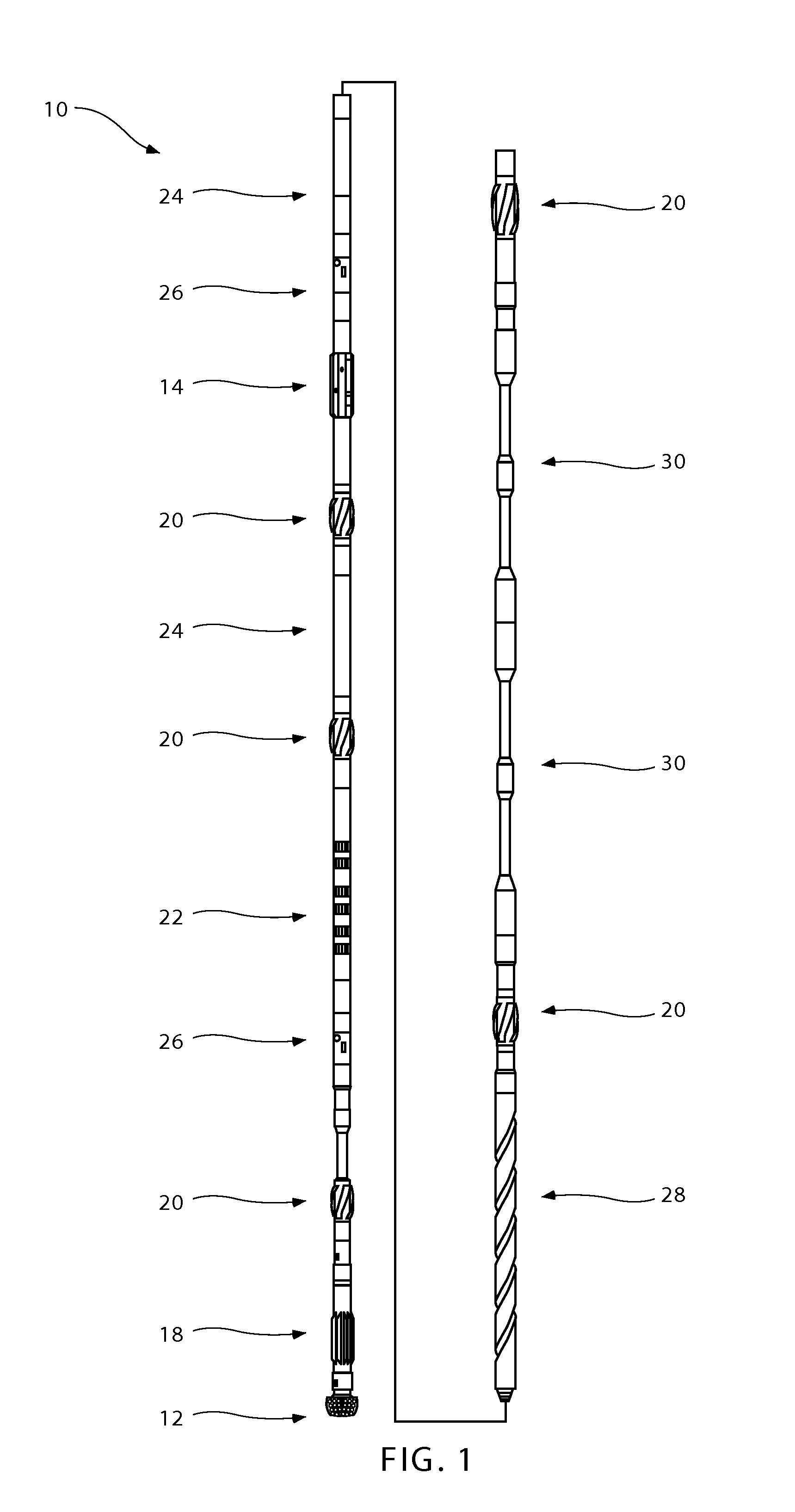
[0076]A bottom hole assembly 10 like that shown in FIG. 1 was used to drill a wellbore as described in I. Thomson et al., “A Systematic Approach to a Better Understanding of the Concentric Hole-Opening Process Utilizing Drilling Mechanics and Drilling Dynamics Measurements Recorded Above and Below the Reamer,” International Association of Drilling Contracts (IADC) and Society of Petroleum Engineers (SPE) Paper No. IADC / SPE 112647 (2008), which was prepared for presentation at the 2008 IADC / SPE Drilling Conference held in Orlando, Fla., U.S.A., between Mar. 4, 2008 and Mar. 6, 2008, which is incorporated by reference herein in its entirety. The bottom hole assembly 10 resulting in improved performance and reduced downhole vibrations relative to a previously known bottom hole assembly configuration.


PUM


Abstract

Methods, systems, and tool assemblies for distributing weight between a bit and a reamer device are disclosed. For example, at least one of the drill bit and the reamer may be configured to selectively distribute a weight-on-bit between the drill bit and the reamer, such as within a predetermined range. Additionally, methods of drilling wellbores may include selectively distributing a weight-on-bit applied to a bottom hole assembly between a drill bit and a reamer of the bottom hole assembly. Also, a reamer may be configured to exhibit a first maximum rate-of-penetration into a relatively hard formation, and a drill bit may be configured to exhibit a second maximum rate-of-penetration into a relatively soft formation that is less than the first maximum rate-of-penetration.

Description

CROSS-REFERENCE TO RELATED APPLICATIONS[0001]This application claims the benefit of U.S. Provisional Patent Application Ser. No. 61 / 148,695, filed Jan. 30, 2009, the disclosure of which is hereby incorporated herein in its entirety by this reference.TECHNICAL FIELD[0002]Embodiments of the present invention relate to methods, systems, and tool assemblies for forming wellbores in subterranean earth formations and, more specifically, to methods, systems, and tool assemblies for forming wellbores in subterranean earth formations using an earth-boring rotary drill bit operating in conjunction with a reamer device for enlarging a diameter of a wellbore created by the earth-boring rotary drill bit.BACKGROUND[0003]Wellbores are formed in subterranean formations for various purposes including, for example, the extraction of oil and gas from a subterranean formation and the extraction of geothermal heat from a subterranean formation. A wellbore may be formed in a subterranean formation using ...

Claims


Application Information

Patent Timeline
IPC IPC(8): E21B7/00E21B10/26
CPCE21B10/26E21B10/32
Inventor RADFORD, STEVEN R.ANDERSON, MARK E.THOMPSON, WILLIAM C.POWERS, JIM R.
Owner BAKER HUGHES INC
Why Eureka
Try Eureka