

Methods and apparatus for reduction of aerodynamic drag
- Summary
- Abstract
- Description
- Claims
- Application Information
AI Technical Summary
Benefits of technology
Problems solved by technology
Method used
Image

Examples
exemplary embodiment 202
[0102]FIG. 3B depicts an additional exemplary embodiment 202 in which apparatus housing 216 is characterized by an upper surface which is partially convex and partially concave.
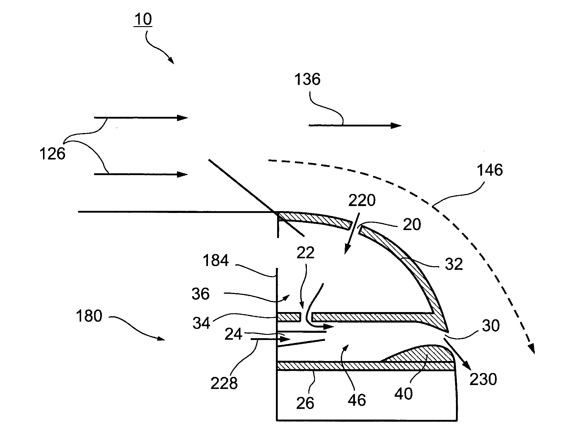
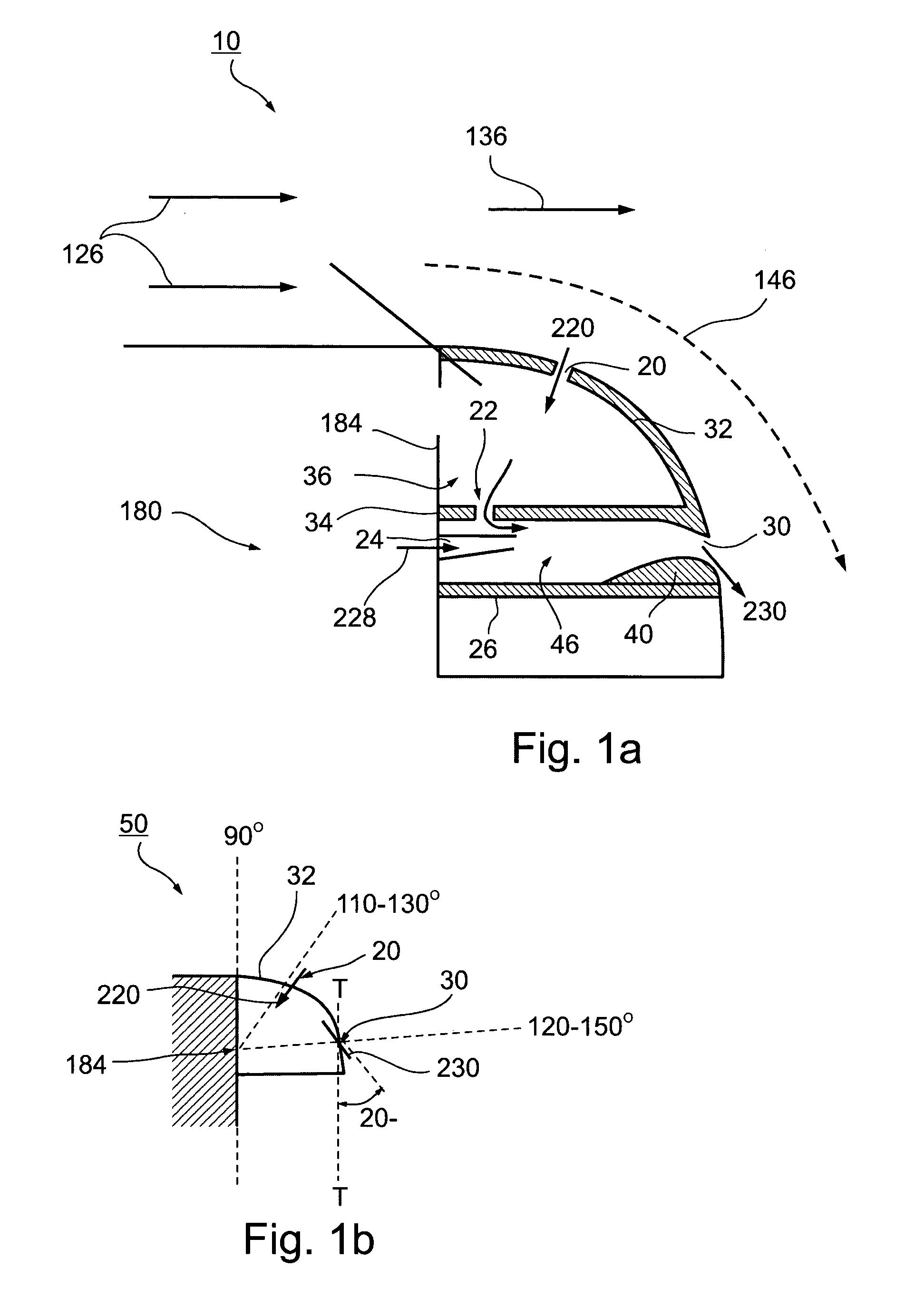
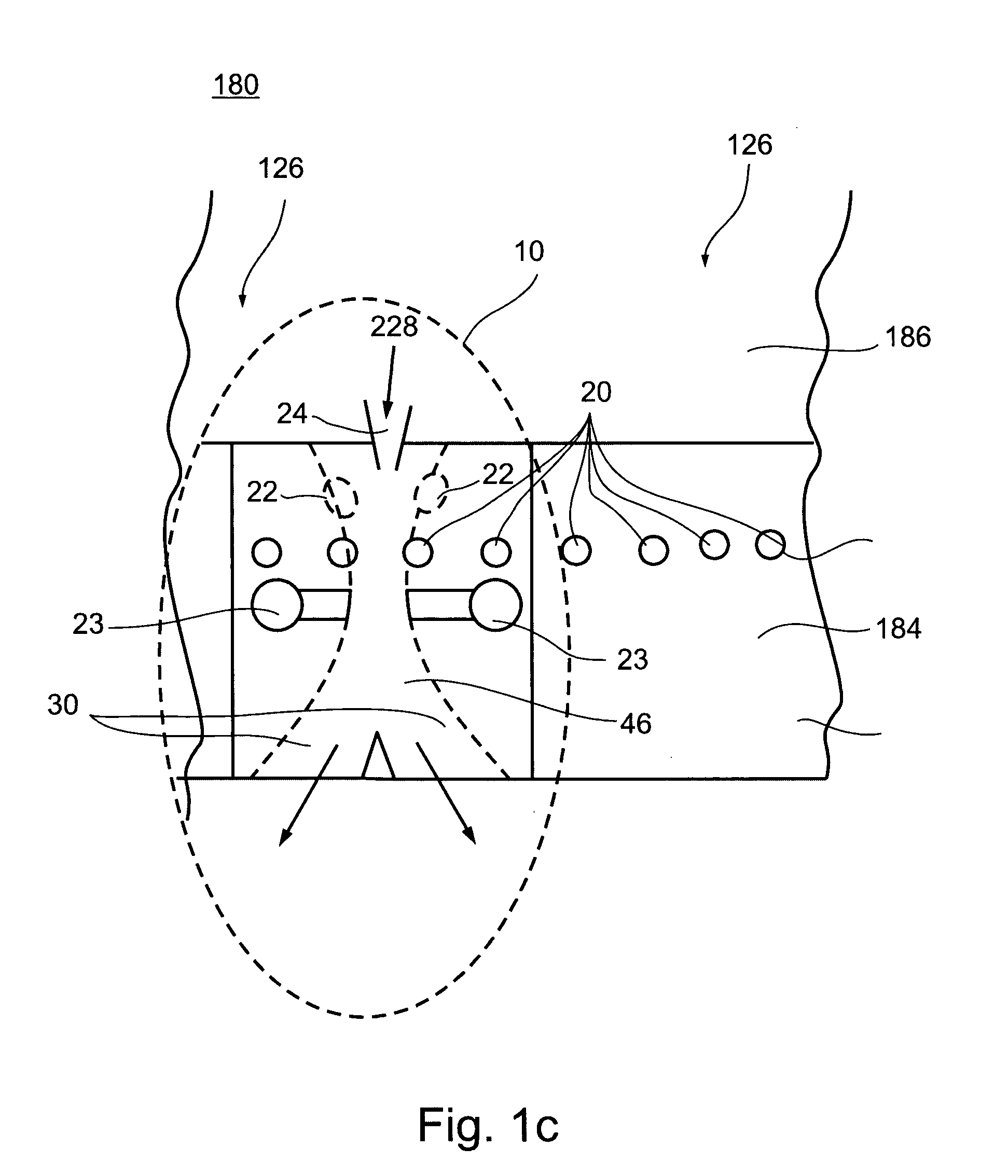
[0103]In an exemplary embodiment of the invention, exit ports 30 (represented here by pulsed flow 230) so that that the pulsed flow 230 impacts the external flow layer at a place where it tends to re-separate downstream of the suction ports 20 (represented by suction flow 220), contributes to an increase in efficiency.
exemplary embodiment 204
[0104]FIG. 3C depicts an additional exemplary embodiment 204 in which apparatus housing 218 is characterized by an upper surface which is substantially concave.
[0105]Exemplary Mounting Configuration
[0106]FIG. 4A is a schematic representation of a mounting configuration 300 for apparatus 110 on blunt body 180 according to an exemplary embodiment of the invention in a lateral cross sectional view. In the depicted embodiment, trailing face 184 comprises a door 330 mounted on a hinge 320. Optionally, apparatus 110 is connected to upper surface 186 of blunt body 180 by apparatus hinge 350 and / or connector 352. In an exemplary embodiment of the invention, apparatus 110 is moved or rotated 390 to permit opening of door 330. Optionally, apparatus 110 moves rotationally with respect to apparatus hinge 350 and / or axially with respect to connector 352. According to various embodiments of the invention, apparatus 110 occupies as little as 10% or as much as 100% a width and / or circumference of r...
PUM
 Abstract
Description
Claims
Application Information