Compact multi-cycle high power microwave generator

a generator and multi-cycle technology, applied in the direction of pulse generator, pulse train generator, pulse technique, etc., can solve the problems of reduced switching number, reduced switching frequency spectrum, and serious switch selection limitation, and achieve the effect of increasing the frequency spectrum of the generated pulse train and variable pulse width

Inactive Publication Date: 2010-08-05
BAE SYST INFORMATION & ELECTRONICS SYST INTERGRATION INC
View PDF13 Cites 6 Cited by
  • Summary
  • Abstract
  • Description
  • Claims
  • Application Information

AI Technical Summary

Benefits of technology

[0042]According to the present invention a compact multi-cycle high power microwave generator is provided by providing a goal-directed interconnection of identical alternately charged two-transmission line sections. Moreover, some variations in width of generating pulses can be achieved for control and increasing the frequency spectrum of the generated pulse train.

Problems solved by technology

This is a serious limitation for switch selection.
However, in these cases the negative effects of switch resistance (Rsw) and switch inductance (Lsw) raise drastically with a decrease in the number of switches.
The coupling of the resulting pulse train to a load, such as an antenna, results in the radiation of a short HPM pulse.
Known multi-cycle microwave generators based on charged transmission lines are not compact due to their schematics / structures.
All of these generators are not compact.
The main problem consists in developing a simple Multi-Cycle Microwave Generator with charged transmission lines, which is compact, required small amount of switches (not more than the number of generating cycles), and with minimum holding voltages on switches that is equal to charging voltages.
All three of these known generators have the same basic circuit (shown in FIG. 4), which suffers from disadvantages, for example: the design is not compact, the required hold-off voltage on each switch is large—equal to double the charging voltage on each transmission line, two switches are required for generating a bipolar pulse (cycle) (i.e., the total number of switches is twice the number of generating cycles), and switches connected in series introduce considerable losses.
Moreover, all switches are no longer positioned on the power flow way and, therefore, their losses are not critical and the number of sections is limited mostly by the conductive losses on transmission lines, i.e., by efficiency.
This design is not compact, especially in the case of using strip transmission lines and very short pulses (around 1-2 ns).
All of these sequential switching generators are also not compact.
Again, however, the design is not compact and two switches are required for generating one bipolar pulse (cycle).
Additionally, this design requires fast switches with specific opening time.
The main disadvantages of such implementations of FWG generators include: the design is not compact, the required hold-off voltage on each switch is large—equal to double the charging voltage.
This design, however, has a complicated, non-compact structure.
Furthermore, this design cannot provide a high repetition rate of generating pulses.
This generator cannot produce a sequential group of bipolar pulses and, therefore, cannot be used for the purpose of effective radiating as known FWG or SSG architectures.
Additionally, negative effects of the switch's resistance and inductance on efficiency and pulse shape are increased due to a relatively large charge transfer through a single switch.
Again, this design suffers from disadvantages, including: non-compact design, deterioration of the pulse shape due to interconnections between cables—especially for frequently required short pulses, deterioration of the efficiency and pulse shape due to the presence of the capacitor, requirement of a high hold-off voltage equal to the double charging voltage, and high negative effects of the switch's resistance and inductance on efficiency and pulse shape due to a relatively large charge transfer through the switch.
This increases efficiency to some extent and improves pulse shape, but decreases reliability.
In addition to the disadvantages discussed above, this design is not preferred for HPM applications for the short pulses and with frequently used strip transmission lines.
This design also suffers from disadvantages mentioned above, for example: non-compact designs, interconnections between cables deteriorate the pulse shape—especially for the frequently required high power short (1-2 ns) pulses especially in the case of low-impedance strip transmission lines, the required hold-off voltage on the switch is equal to double the charging voltage, high negative effects of the switch's resistance and inductance on efficiency and pulse shape due to a relatively large charge transfer through the switch (increases with number of pulses), and parallel connected switches typically are necessary.

Method used


Image

  • Compact multi-cycle high power microwave generator
  • Compact multi-cycle high power microwave generator
  • Compact multi-cycle high power microwave generator

Examples


Embodiment Construction

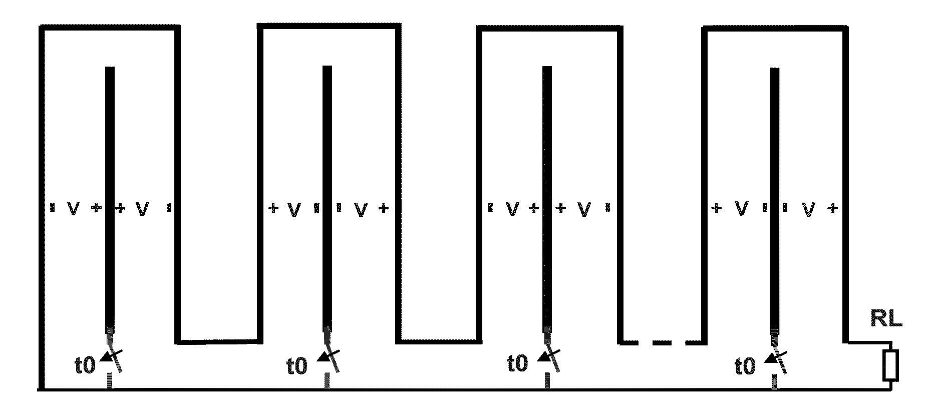
[0081]One embodiment of the present invention is illustrated in FIG. 9. In this generator, N alternately charged sections with equal characteristic impedances (the same as load impedance) provide N bipolar pulses on the load. All switches should be closed simultaneously. Also, switches with the same potential with respect to a common conductor could be connected together and replaced by a single switch in a proper design. The interconnection transmission lines between oppositely charged line sections are non-charged and should have the same impedance as the charged lines. These lines induce separation in time between bipolar pulses. Because all waves propagate inside the structure, all sections could be combined with common conductors in a very compact design without any lines between sections, as illustrated in FIG. 10.

[0082]One of the significant improvements over known multi-cycle generators is simultaneously implementing compactness, minimum hold-off voltages on switches, and a ...


PUM


Abstract

A compact multi-cycle high power microwave generator and a method of using the generator to generate microwave signals is disclosed and claimed. The apparatus includes one or more charged transmission line sections. Each transmission line section includes a first conductor that is section-specific and a second conductor that is common to all of the sections. A switch is associated with each section, each switch being operatively connected to a respective one of the first conductors. The apparatus includes third, common conductor that is not charged and that is operatively connected to each of the first conductors through its respective switch. The apparatus further includes a load, with the second conductor, the third conductor, and the load being operatively connected. Thus, the number of section-specific conductors, the number of charged transmission line sections, and the number of switches are all equal. Engagement of the switches generates a multi-cycle microwave pulse. Aspects, such as wavelength, frequency, and spacing, of the generated wave forms can be varied by including non-charged transmission lines intermediate the transmission line sections or varying the lengths of individual transmission line sections or varying the switching time.

Description

CROSS-REFERENCE TO RELATED APPLICATIONS[0001]This application claims the benefit of U.S. Provisional Patent Application No. 61 / 148,643 filed on Jan. 30, 2009, which is incorporated herein by reference in its entirety.BACKGROUND OF THE INVENTION[0002]1. Field of the Invention[0003]The present invention relates to a method and apparatus for generating microwaves and, more particularly, the present invention relates to a microwave source and method for generating a train of bipolar pulses.[0004]2. Description of the Related Art[0005]High power microwave (HPM) pulse generators for radiating purposes should generate bipolar pulse(s) due to the absence of non-radiated dc and low-frequency components at their frequency spectrum. With respect to the number of generating pulses and corresponding basic structures, HPM pulse generators are divided in two categories:[0006]1. Monocycle (Single Bipolar pulse) Generators[0007]2. Multi-cycle (Train of Bipolar pulses) Generators[0008]The best multi-...

Claims


Application Information

Patent Timeline
Patent Type & Authority Applications(United States)
IPC IPC(8): H03K3/57
CPCH03K3/86H03K3/53
Inventor LONDON, SIMON Y.
Owner BAE SYST INFORMATION & ELECTRONICS SYST INTERGRATION INC
Why Eureka
Try Eureka