Hermetically sealed RFID microelectronic chip connected to a biocompatible RFID antenna

a microelectronic chip and antenna technology, applied in the field of implantable and biocompatible radio frequency identification (rfid) tags, can solve the problems of limited information so provided, difficult identification, and inability to meet the needs of patients,

Active Publication Date: 2010-08-05
WILSON GREATBATCH LTD
View PDF30 Cites 88 Cited by
  • Summary
  • Abstract
  • Description
  • Claims
  • Application Information

AI Technical Summary

Benefits of technology

[0023]The antenna may be wound around a ferrite-based core comprising a high temperature sintered ferrite-based material having a biocompatible dielectric material at least partially coating the ferrite-based material. Such biocompatible dielectric material may comprise parylene, ETFE, PTFE, polyimide, polyurethane, or silicone. Preferably, the ferrite-based core is comprised of a ferrite material that will not exhibit permanent remanence after exposure to MRI fields.

Problems solved by technology

The information so provided is limited due to space and typically includes only the manufacturer and model number of the implanted device.
However, such forms of identification are often not reliable.
In addition, there have been a number of situations where the patient (due to dementia or Alzheimer's, etc.) cannot clearly state that he or she even has a pacemaker.
If the patient is comatose, has low blood pressure, or is in another form of cardiac distress, this presents a serious dilemma for the ER.
What happens next is both laborious and time consuming.
It is a very difficult surgical procedure to actually remove leads from the heart once they are implanted.
This is because the distal TIP and other areas of the leads tend to become embedded and overgrown (encapsulated) by tissues.
It often takes very complex surgical procedures, including lasers or even open heart surgery, to remove such lead wire systems.
However, it is also quite common for leads to fail for various reasons.
They could fail due to breakdown of electrical insulation or they could migrate to an improper position within the heart.
Abandoned leads can be quite a problem during certain medical diagnostic procedures, such as MRI.
It has been demonstrated in the literature that such leads can greatly overheat due to the powerful magnetic fields induced during MRI.
In other words, it would be dangerous for a patient with a lead wire designed for 3 Tesla to be exposed to a 1.5 Tesla system.
However, none of the current RFID tags have been designed to have long term reliability, hermeticity, and biocompatibility within the body fluid environment.
However, as will be discussed more fully below, none of these materials provide a truly hermetic seal against body fluids.
The read range of such antennas, particularly for low frequency (LF) and high frequency (HF) readers tends to be very short.
Obviously, neither copper nor solder joints are biocompatible or even reliable for human body implants.
When exposed to body fluids, copper causes corrosion problems as well the tin and lead that is typically used in solders.
These materials, when leached out can even become toxic to the human body.
However, when one fully contemplates hermetically sealing an RFID chip with a very large multi-turn loop antenna, one realizes that such an approach becomes entirely impractical.
The hermetic seal package would simply be too large to be effectively associated with a medical implant.

Method used


Image

  • Hermetically sealed RFID microelectronic chip connected to a biocompatible RFID antenna
  • Hermetically sealed RFID microelectronic chip connected to a biocompatible RFID antenna
  • Hermetically sealed RFID microelectronic chip connected to a biocompatible RFID antenna

Examples


Embodiment Construction

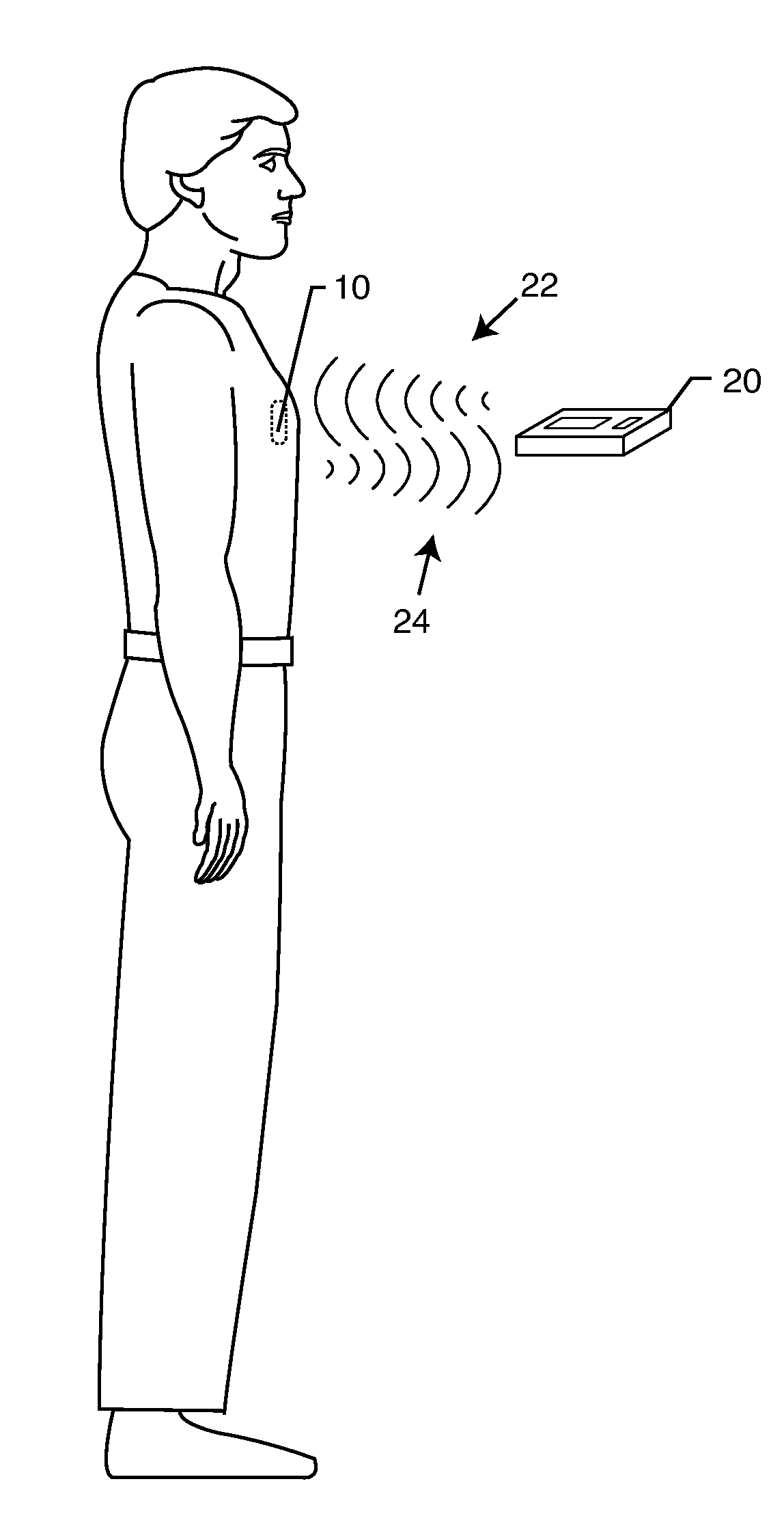
[0056]The present invention is directed to a radio frequency identification (RFID) system for use with active implantable medical devices (AIMDs) and an associated RFID tag. Specifically, the RFID system comprises an RFID tag implanted in a patient's body and associated with an implanted AIMD, and an interrogator in communication with the RFID tag. The novel tag comprises an electronic RFID chip disposed inside the hermetically sealed housing of an AIMD, and an external biocompatible antenna.

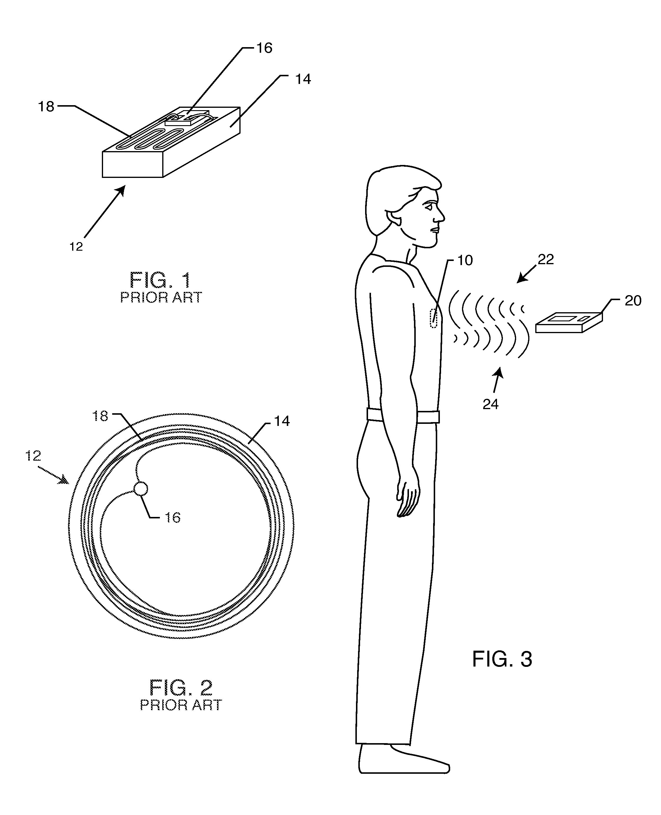
[0057]FIG. 3 is an outline drawing of an adult male pacemaker patient with an AIMD 10. The location for the AIMD 10, shown by a dashed ellipse, is typical of a right or left pectoral muscle implant. Right and left pectoral muscle implants are typical for a cardiac pacemaker or implantable cardioverter defibrillator (ICD). The right and left pectoral muscle region is chosen due to the easy access to the cephalic or subclavian veins for transvenous insertion of lead wires and electrodes down into ...


PUM


Abstract

An implantable radio frequency identification (RFID) tag includes a hermetically sealed biocompatible housing for an active implantable medical device (AIMD), an RFID microelectronics chip is disposed within the housing, and a biocompatible antenna extends from the RFID microelectronic chip and exteriorly of the housing. In a preferred form of the invention, the antenna is disposed within a header block of the AIMD, and the RFID chip is disposed within the AIMD housing.

Description

BACKGROUND OF THE INVENTION[0001]This invention relates generally to methods of identifying implanted medical devices. More specifically, this invention relates to implantable and biocompatible radio frequency identification (RFID) tags and associated antennas which may be used with medical devices or for general personal identification purposes.[0002]There are known in the art various methods for identifying implanted medical devices. One such method is the use of X-ray identification tags encapsulated within header blocks of pacemakers or implantable cardioverter defibrillators (ICD). Such X-ray identification tags can be read on an X-ray of the implanted device and provide information to the physician. The information so provided is limited due to space and typically includes only the manufacturer and model number of the implanted device.[0003]It would be beneficial if physicians were able to obtain additional information about an implanted device and / or a patient from an implant...

Claims


Application Information

Patent Timeline
Patent Type & Authority Applications(United States)
IPC IPC(8): H04Q5/22
CPCA61B5/0031A61B19/44A61B2019/448A61B2562/08A61N1/37G06K19/07749A61N1/37223A61N1/37229A61N1/3752A61N1/3754A61N1/3718A61B90/90A61B90/98
Inventor STEVENSON, ROBERT A.FRYSZ, CHRISTINE A.
Owner WILSON GREATBATCH LTD
Why Eureka
Try Eureka