Hearing device

a hearing device and electronic technology, applied in the field of hearing devices, can solve the problems of affecting the frequency of hearing devices, and affecting the operation of hearing devices, so as to reduce the frequency of a portion, reduce the amount of undesired high-frequency components, and save switching energy in the device

Active Publication Date: 2010-08-05
OTICON
View PDF6 Cites 14 Cited by
  • Summary
  • Abstract
  • Description
  • Claims
  • Application Information

AI Technical Summary

Benefits of technology

[0045]Advantageously, the method further comprises the step of reducing the frequency of a portion of the electrical signals being modified. This allows for generating electrical output signals of a lower frequency and hence a lower switching frequency, thus saving switching energy in a device used for generating the electrical output signals.
[0046]Advantageously, the method further comprises the step of low-pass filtering a portion of the electrical output si...

Problems solved by technology

A problem of the prior art hearing devices is that the typical receivers are relatively large, which is especially undesired with devices intended to be worn by a person in or close to the ear.
Furthermore, typical receivers are relatively heavy, which renders the hearing devices relatively susceptible to damage due to mechanical shocks, e.g. if they are dropped on a hard floor.
The typical receivers also comprise delicate structures, some of which are moving and which are complicated and thus expensive to manufacture.
The moving parts of typical receivers induce feedback, which may cause the hearing devices to howl or whistle, and the methods, which are typically implemented to reduce or prevent such howling or whistling, produce audible artefacts in the acoustical signals presented to the wearers of the devices and may even affect the wearer's ability to understand speech in some types of acoustical environm...

Method used


Image

  • Hearing device
  • Hearing device
  • Hearing device

Examples


first embodiment

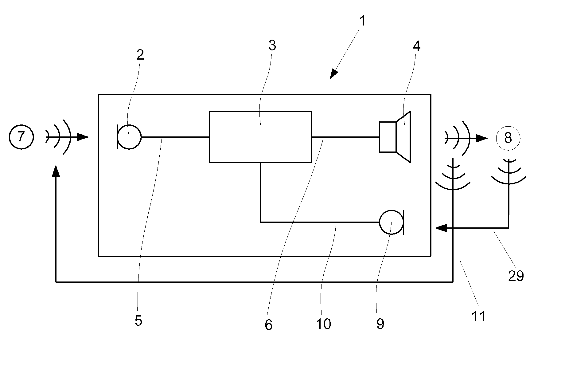
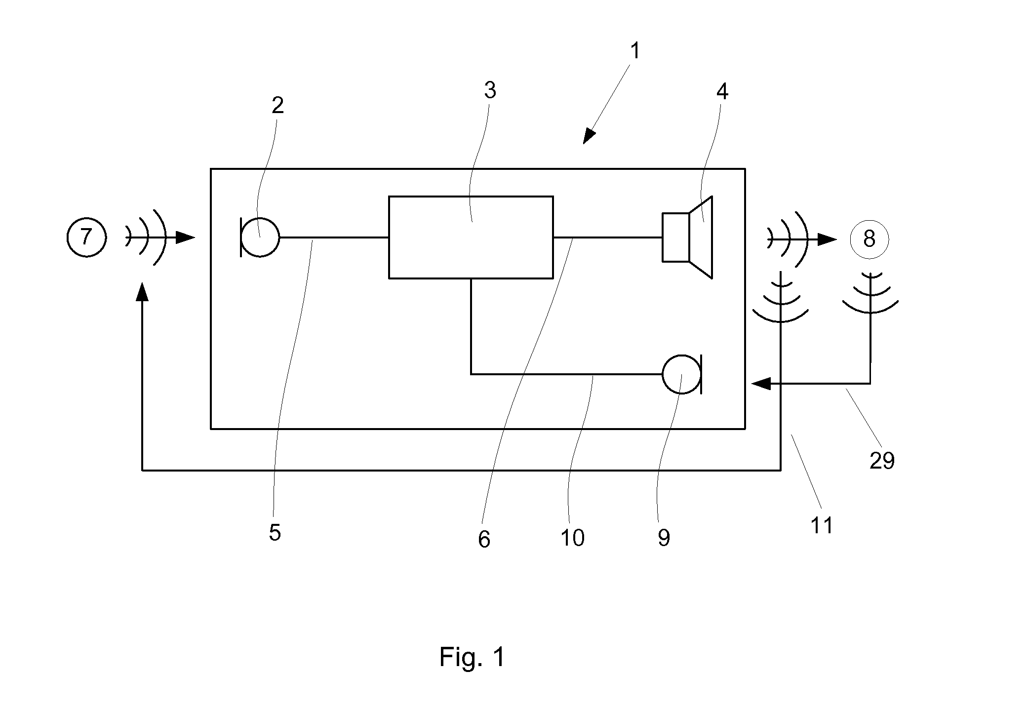
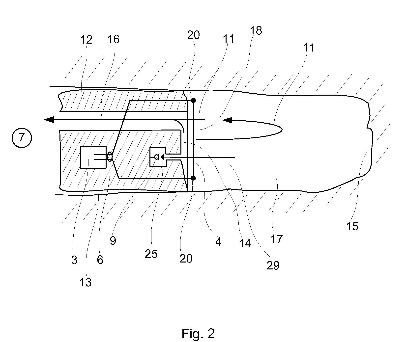
[0062]The ear plug 12 shown in FIG. 2 is comprised in a hearing device 1 (see FIG. 1) according to the present invention. The ear plug 12 may constitute the entire hearing device 1 or it may comprise only parts hereof, e.g. the receiver 4 and a part of the signal conditioning means 3. In the latter case, the ear plug 12 may be connected to the remaining parts of the hearing aid 1 via e.g. an electrical or a wireless connection (not shown). The ear plug 12 is located in an ear canal 13 of a person, whereby it separates an inner portion 17 of the ear canal 13 from the person's surroundings 7. The ear plug 12 has an inwardly directed surface 14 facing the inner portion 17 of the ear canal 13 and thus also facing the tympanum 15 at the innermost end of the ear canal 13. The receiver 4 comprises a thermoacoustical transducer 18 comprising a disc-shaped body formed from a carbon nanotube thin-film similar to the ones described by Lin Xiao et al. The carbon nanotube thin-film comprises car...

second embodiment

[0064]The ear plug 12 partly shown in FIG. 3 is comprised in a hearing device 1 (see FIG. 1) according to the present invention. The thermoacoustical transducer 18 comprises a three-dimensional body substantially in the shape of a toroid with its axis of symmetry 27 arranged substantially perpendicular to the inwardly directed surface 14. The carbon nanotube fibres 18 are enclosed in a membrane 22 formed from a material suitable for allowing acoustical energy to pass through itself and at the same time protecting the fibres against e.g. ear wax, moisture and dust. Suitable materials may be selected from e.g. rubber, silicone or various polymer-based materials. An opening 23 through the centre of the toroid extends the vent 16 towards the inner portion 17 of the ear canal 13 (see FIG. 2). Shaping the thermoacoustical transducer 18 as a three-dimensional body allows for incorporating more carbon nanotube fibres in the transducer 18, thus allowing a higher acoustical signal output than...

third embodiment

[0065]The ear plug 12 shown in FIG. 4 is comprised in a hearing device 1 (see FIG. 1) according to the present invention. The carbon nanotube fibres of the thermoacoustical transducer 18 are incorporated in a resilient member 24, which has the shape of a circular cylinder and is dimensioned to close the ear canal 13 when inserted therein, whereby it separates an inner portion 17 of the ear canal 13 from the person's surroundings 7 (see FIG. 2). The resilient member 24 is formed from a foam material, which allows acoustical signals to travel relative unhindered through it. The fibres may be dispersed or distributed evenly in the resilient member 24 or e.g. concentrated in specific locations or volumes within the resilient member 24. This allows for a large flexibility in shaping the radiating body of the thermoacoustical transducer 18. The remaining parts of the ear plug 12 are located in a housing 28, which has a smaller diameter than that of the ear canal 13, thus allowing the vent...


PUM


Abstract

The invention relates to a hearing device 1 adapted for placement in, at or near a person's ear, the hearing device 1 comprising a microphone 2, a receiver 4 and a signal conditioning means 3 connected to the microphone 2 and to the receiver 4, the microphone 2 being arranged for receiving acoustical signals from the person's surroundings 7 and converting these acoustical signals into electrical signals and the receiver 4 being arranged for converting electrical signals into acoustical signals and transmitting these into the ear's ear canal 13. The object of the present invention is to provide a small, light-weight hearing device 1. The problem is solved in that the receiver 4 comprises a thermoacoustical transducer 18, which allows for a receiver 4 which may take up less space in the hearing device 1 and may have a smaller weight. This has the advantage of allowing the hearing device 1 to be small and light-weight, thus providing an improved wearing comfort. The invention may e.g. be used in hearing aids for compensating a person's loss of hearing capability.

Description

TECHNICAL FIELD[0001]The present invention relates to a hearing device. More specifically, the present invention relates to an electronic hearing device, such as e.g. a hearing aid, a listening device or an ear protection device, which receives acoustical signals from a person's surroundings, modifies the acoustical signals electronically and transmits the modified acoustical signals into the person's ear or ear canal.[0002]The invention may e.g. be useful in applications such as a hearing aid for compensating a person's loss of hearing capability; a listening device for augmenting a person's hearing capability or an ear protection device for protecting a person's ear against damage from loud sounds.BACKGROUND ART[0003]The following account of the prior art relates to one of the areas of application of the present invention.[0004]Electronic hearing devices, such as hearing aids, listening devices and ear protection devices, are well known in the art. Hearing aids and listening devic...

Claims


Application Information

Patent Timeline
IPC IPC(8): H04R25/00
CPCH04R23/002
Inventor RASMUSSEN, KARSTEN BOPETERSEN, SVEND OSCAR
Owner OTICON
Why Eureka
Try Eureka