Eureka AIR delivers breakthrough ideas for toughest innovation challenges, trusted by R&D personnel around the world.

Image processing apparatus, program, recording medium, and image forming apparatus

Inactive Publication Date: 2010-08-05
CANON KK
View PDF4 Cites 2 Cited by
  • Summary
  • Abstract
  • Description
  • Claims
  • Application Information

AI Technical Summary

Benefits of technology

[0006]A principal object of the present invention is to provide an image processing apparatus capable of making glossiness in a designated area lower than glossiness in another area even in the case where the glossiness of a sheet on which a transparent toner image is to be formed is low.
[0015]image data generating means for generating the image data to be sent to the image forming portion depending on the information obtained by the sheet information obtaining means so that the glossiness in the area obtained by the area information obtaining means is lowered relatively.

Problems solved by technology

However, in the case where the glossiness of the sheet on which the transparent toner image was to be formed was low, the glossiness in the area in which the transparent toner image was formed was unable to be lowered by forming the transparent toner image in the designated area.

Method used


Image

  • Image processing apparatus, program, recording medium, and image forming apparatus
  • Image processing apparatus, program, recording medium, and image forming apparatus
  • Image processing apparatus, program, recording medium, and image forming apparatus

Examples


embodiment 1

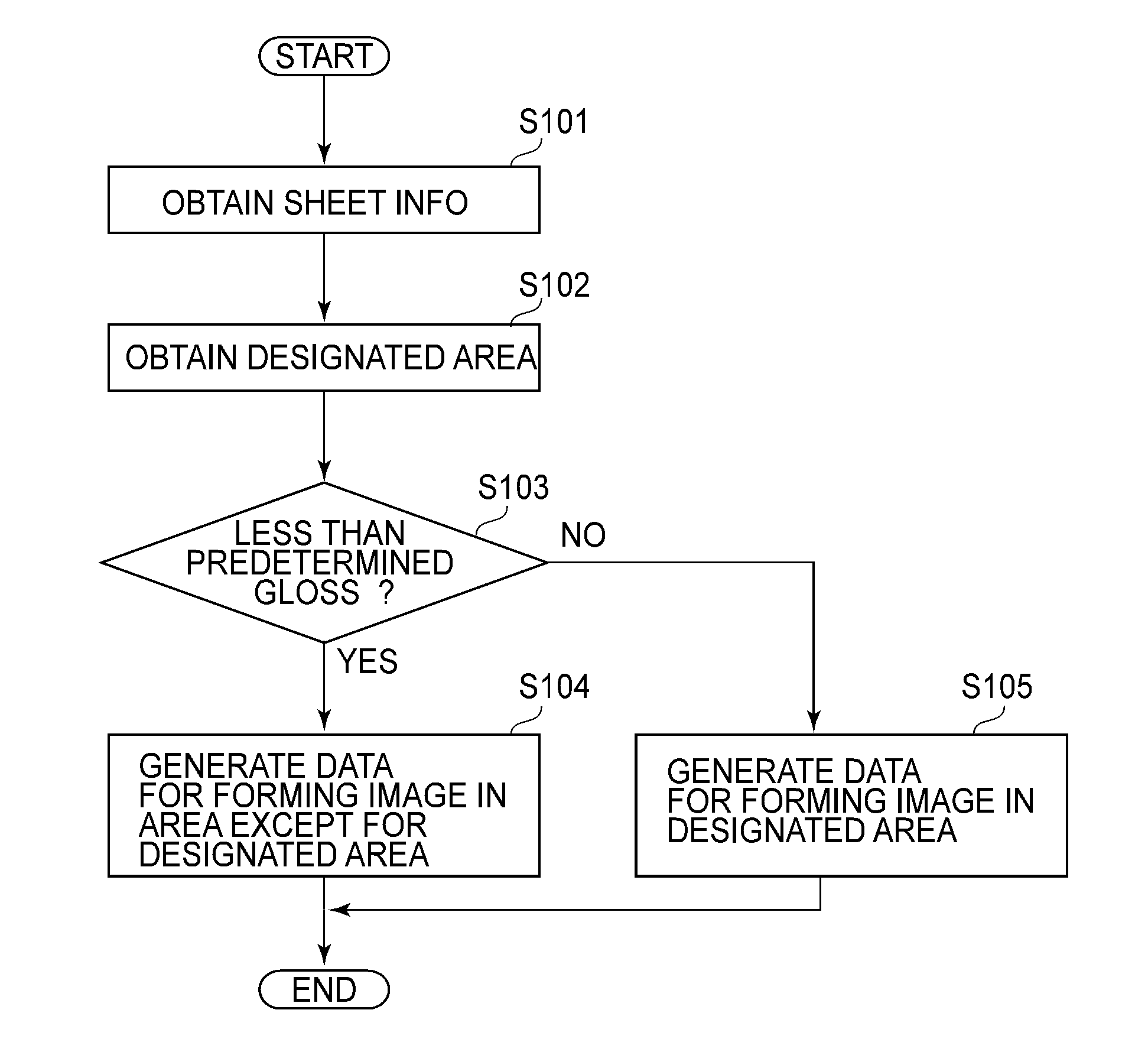
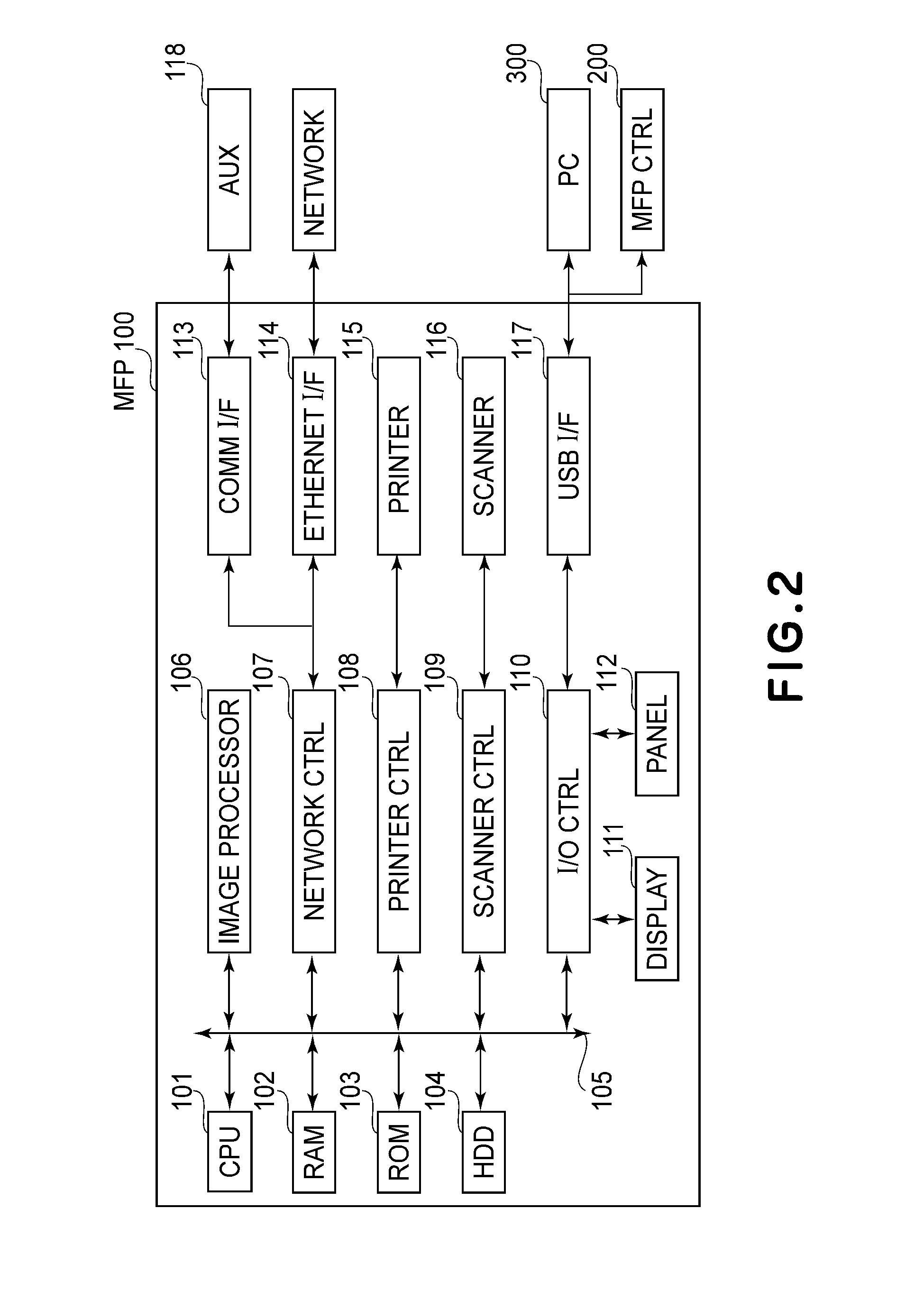
[0040]Embodiment 1 will be described below. First, a system constitution will be described. Then, respective constituent elements constituting the system will be described. Thereafter, an operation of the system will be described along a flow chart. Hereinafter, an image processing system refers to an information processing system for generating image data used for printing at a printer portion 115 (FIG. 3) as an image forming portion. Further, an image forming system refers to the image processing system including the printer portion 115.

(Image Forming System Constitution)

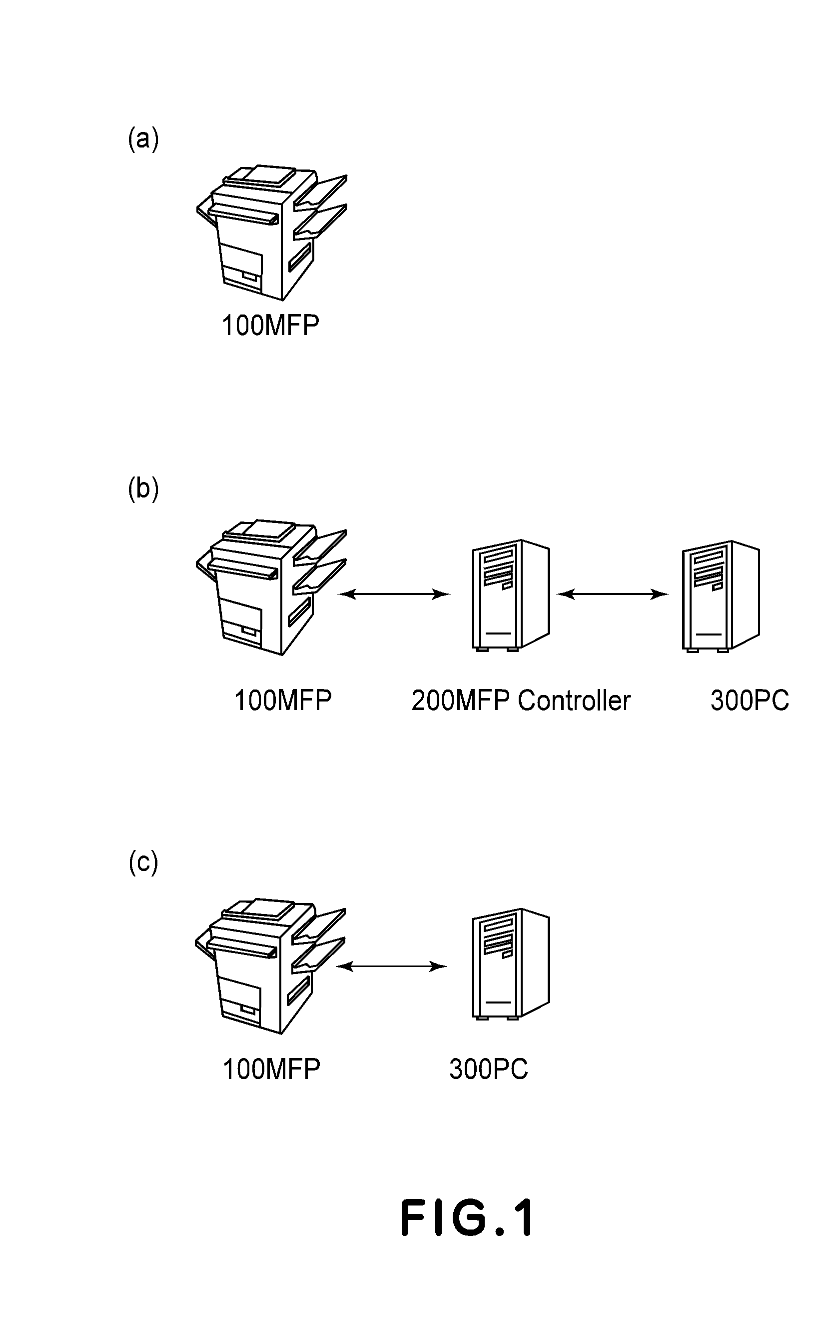
[0041]FIGS. 1(a), 1(b) and 1(c) are schematic views each showing an example of a constitution of the image forming system. The image forming system consists of the following three apparatuses. A first is an MFP 100 as an image forming apparatus. A second is an MFP controller 200 as an external controller. A third is a PC 300 as the information processing apparatus. The image forming system is constituted by the ab...

embodiment 2

[0166]Portions or means similar to those in Embodiment 1 are represented by the same reference numerals or symbols, thus being omitted from description. In this embodiment, the image forming system is constituted as shown in FIG. 1(b). Further, the image processing for generating the transparent image data is executed by the MFP controller 200.

[0167]Hardware configurations of the PC 300 and the MFP controller 200 which constitutes the image forming system will be described.

[0168]The PC 300 constituting the image forming system is an example of an external terminal capable of sending print instructions to the MFP 100. For that purpose, it is also possible to use other terminals capable of sending the print instructions to the MFP 100 as an alternative to the PC. For example, it is possible to use portable information terminals such as a WS (work station) and a PDA (personal digital assistant) as the alternative to the PC.

(Hardware Configuration of PC)

[0169]FIG. 14 is a block diagram ...

embodiment 3

[0214]With respect to portions or means similar to those in the above-described embodiments, the portion or means are represented by the same reference numerals or symbols, thus being omitted from description.

(Role of Glossiness Sensor in this Embodiment)

[0215]In this embodiment, the image processing for generating the transparent image data is executed by the PC 300. Further, in this embodiment, the glossiness sensor 15 is disposed at positions B, C and D in the MFP 100 shown in FIG. 3.

[0216]The glossiness sensor 15 as the glossiness detecting means can measure the glossiness of the sheet surface. However, the type of the sheet cannot be discriminated by the glossiness sensor 15. That is, the glossiness sensor 15 can measure the sheet glossiness as being “5%” but cannot discriminate the type of the sheet. For example, the glossiness sensor 15 cannot discriminate whether the paper (sheet) with the glossiness of “5%” is “sheet with 5%-glossiness mfd. by A CO.” or “sheet with 5%-gloss...


PUM


Abstract

In the case where a sheet on which a transparent toner image is to be formed has low glossiness, when the transparent toner image is formed in a area in which a user wishes to partly lower the glossiness, the glossiness in the area in which the user wishes to lower the glossiness is increased. For that reason, a print as desired by the user cannot be obtained by fixing the transparent toner image in an area corresponding to the area in which the user wishes to lower the glossiness.In the case where the sheet to be subjected to printing is judged as low glossy paper, the transparent toner image is placed in an image formable area except for the area in which the user wishes to lower the glossiness.

Description

FIELD OF THE INVENTION AND RELATED ART[0001]The present invention relates to an image processing apparatus for generating image data for transparent toner to be used when an image forming portion forms a transparent image, a program for causing an information processing apparatus or an processing system to function as the processing apparatus image, a recording medium storing the program, and an image forming apparatus.[0002]In a recent printing market, improvement in quality of a print by increasing glossiness in a designated area has been required. That is, there is a demand to make the glossiness in the designated area higher than the glossiness in another area.[0003]For example, in an image forming apparatus described in Japanese Laid-Open Patent Application (JP-A) Hei 4-338984, the demand is met by using the transparent toner. Specifically, an image of the transparent toner is selectively formed in the designated area to partly increase the glossiness of the print. As a result,...

Claims


Application Information

Patent Timeline
IPC IPC(8): G03G15/00G06F3/12
CPCG03G15/5029G03G2215/0081G06K15/02G03G15/0194G06K15/1848G03G15/6585G03G2215/00805G06K15/186
Inventor SHIOZAWA, MOTOHIDE
Owner CANON KK
Why Eureka
Eureka Blog
Learn More