Mobile vacuum excavation process
a mobile vacuum and excavation technology, applied in the direction of loading/unloading vehicle arrangment, cleaning equipment, transportation items, etc., can solve the problems of filter not getting proper maintenance, current state of the art mobile vacuum boring, and large and cumbersome excavation system
- Summary
- Abstract
- Description
- Claims
- Application Information
AI Technical Summary
Benefits of technology
Problems solved by technology
Method used
Image
Examples
first embodiment
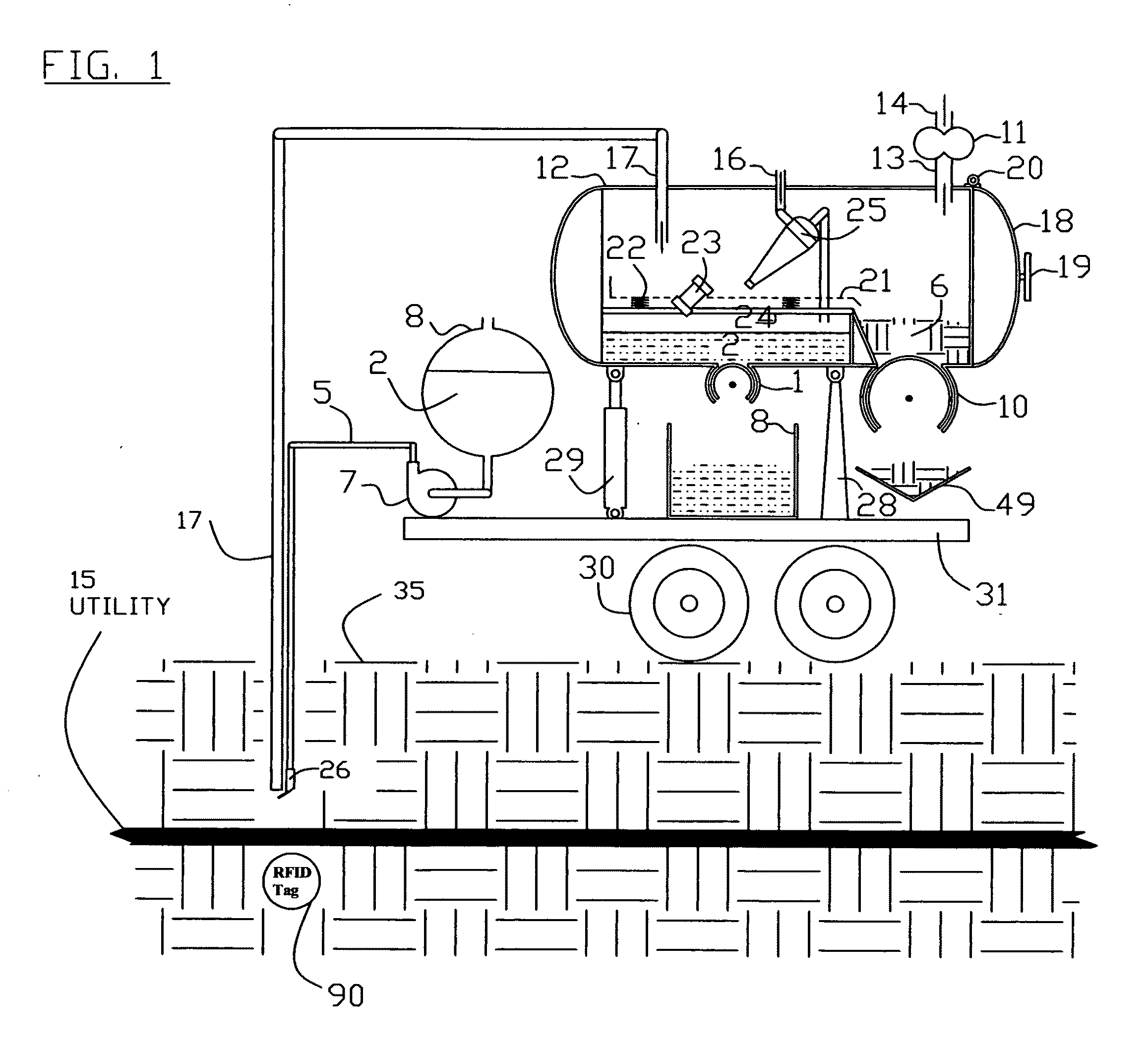
[0098]FIG. 1 shows the invention, being one example of various possible arrangements of apparatus within a vacuum container 12 for the purpose of accomplishing a method of separating solids 6 or liquids 2 by predetermined category and then dispensing said solids 6 or liquids 2 using a dispensing means 1 without eliminating the vacuum environment within the vacuum container 12. In FIG. 1, the apparatus of the present invention include a vacuum container 12, a vacuum producing means 11, a conduit 13 to allow air to move from vacuum container 12 to vacuum producing means 11, a second conduit 14 dispenses air from the vacuum producing means 11. Vacuum container 12 has an access door 18 having a hinge 20 and a latching means 19. Solids 6 or liquids 2 are vacuumed into vacuum container 12 by means of a vacuum conduit 17. In FIG. 1, the ground 35 is earthen dirt. Liquid 2, which has been stored in container 8, is pumped by pump 7 through pump discharge conduit 5 to a spray nozzle 26. The p...
second embodiment
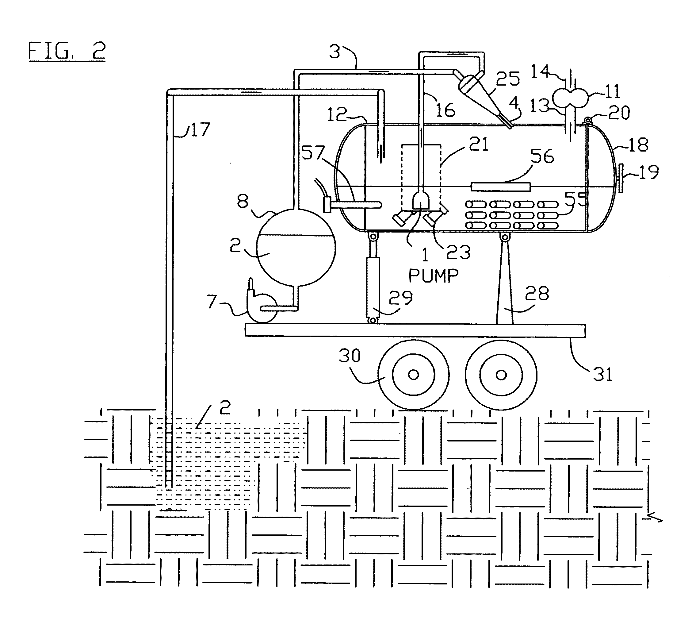
[0099]In the invention shown in FIGS. 2 and 3, the screen 21 is formed in the shape of a cylinder. The solids 6 and liquids 2 which are vacuumed through conduit 17, are deposited into vacuum container 12 around the vibrated screen well 21. The solids 6 which cannot pass through the screen well 21, remain in the vacuum container 12 to be dumped out through access door 18 when it is opened and cylinder 29 is extended. Liquid 2 passes through screen 21 thus dewatering the solids 6 which remain in vacuum container 12. Liquid 2, which passes through screen 21, is dispensed from vacuum container 12 by means of liquid dispenser 1, which in this example is a pump. The liquid 2 passes through conduit 16 and into hydro-cyclone 25 where the solids 6 and liquid 2 separation is further refined. The solids 6 are discharged through solids discharge conduit 4 into vacuum container 12 and liquids are discharged through conduit 3 which discharges into a liquid 2 storage container 8 thus providing a m...
third embodiment
[0101]In the invention shown in FIG. 4, the solids 6 are passed through a solids grinder 27 in order to reduce the solids 6 size to a predetermined size before being dispensed by a solids dispenser 10 which in this example is a progressive cavity screw. The dispensed solids are collected in solids receiver container 9 to be hauled off. The liquid 2 is shown being dispensed by liquid dispenser means 1, which in this example is a diaphragm pump. The recycled liquid 2 is pumped through hose reel 37 by transfer pump 7 to a water jetter 39 spraying a water jet 40, thus cleaning drain pipe 38 with recycled water as it moves.
[0102]The recycled liquid 2 along with solids 6 washed from drain pipe 38 are vacuumed up by the vacuum conduit 17 which is shown as an articulated powered vacuum conduit boom 36. The articulated powered boom 36 also has means to place the jetter 39 into location down a manhole 59 and into a lateral drainage conduit 38 and dispense the jetter conduit 58. In this exampl...
PUM
 Abstract
Description
Claims
Application Information
 - R&D
- Intellectual Property
- Life Sciences
- Materials
- Tech Scout
- Unparalleled Data Quality
- Higher Quality Content
- 60% Fewer Hallucinations
Browse by: Latest US Patents, China's latest patents, Technical Efficacy Thesaurus, Application Domain, Technology Topic, Popular Technical Reports.
© 2025 PatSnap. All rights reserved.Legal|Privacy policy|Modern Slavery Act Transparency Statement|Sitemap|About US| Contact US: help@patsnap.com


