Magnetic resonance imaging apparatus and program

a magnetic resonance imaging and program technology, applied in the field of magnetic resonance imaging apparatus, can solve the problem of not wanting to visualize background tissues as much as possibl

Active Publication Date: 2010-08-05
GE MEDICAL SYST GLOBAL TECH CO LLC
View PDF15 Cites 10 Cited by
  • Summary
  • Abstract
  • Description
  • Claims
  • Application Information

AI Technical Summary

Benefits of technology

[0008]In some embodiments, transverse magnetization of a second background tissue long in T1 value is flipped to longitudinal magnetization before the execution of the following pulse sequence after the acquisition of magnetic resonance signals. Consequentially, the second background tissue long in T1 value can be suppressed efficiently even though variations occur in a waiting time from the end of a pulse sequence to the start of the following pulse sequence.

Problems solved by technology

Since it becomes hard to visually identify arterial blood when background tissues (such as fat and cerebrospinal fluid) are visualized together in addition to the arterial blood, there occurs a case where it is not desired to visualize the background tissues as much as possible.
The method according to the non-patent document 1 is however accompanied by a problem that there is a need to create a difference image in order to obtain an MRA image in which background tissues such as cerebrospinal fluid have been suppressed, and an imaging time is hence taken therefor.

Method used


Image

  • Magnetic resonance imaging apparatus and program
  • Magnetic resonance imaging apparatus and program
  • Magnetic resonance imaging apparatus and program

Examples


Embodiment Construction

[0041]Although a mode for carrying out the invention will hereinafter be explained, the invention is not limited to the following mode.

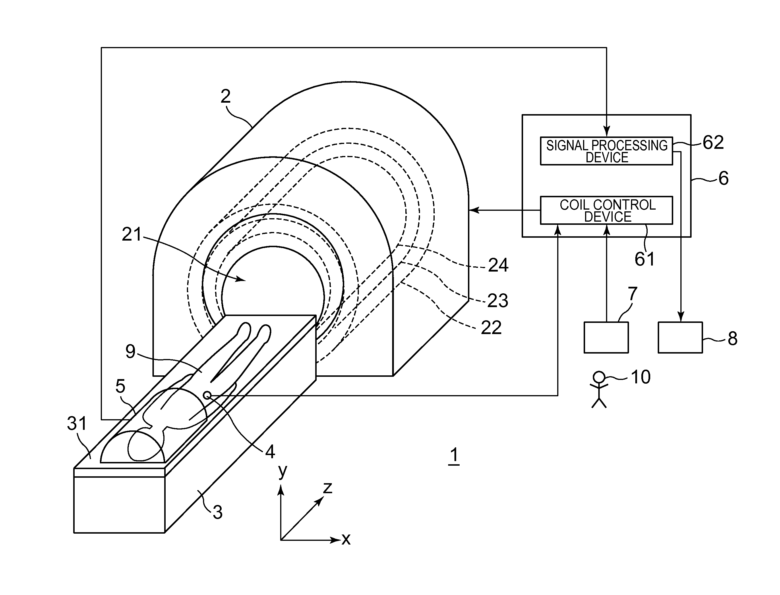
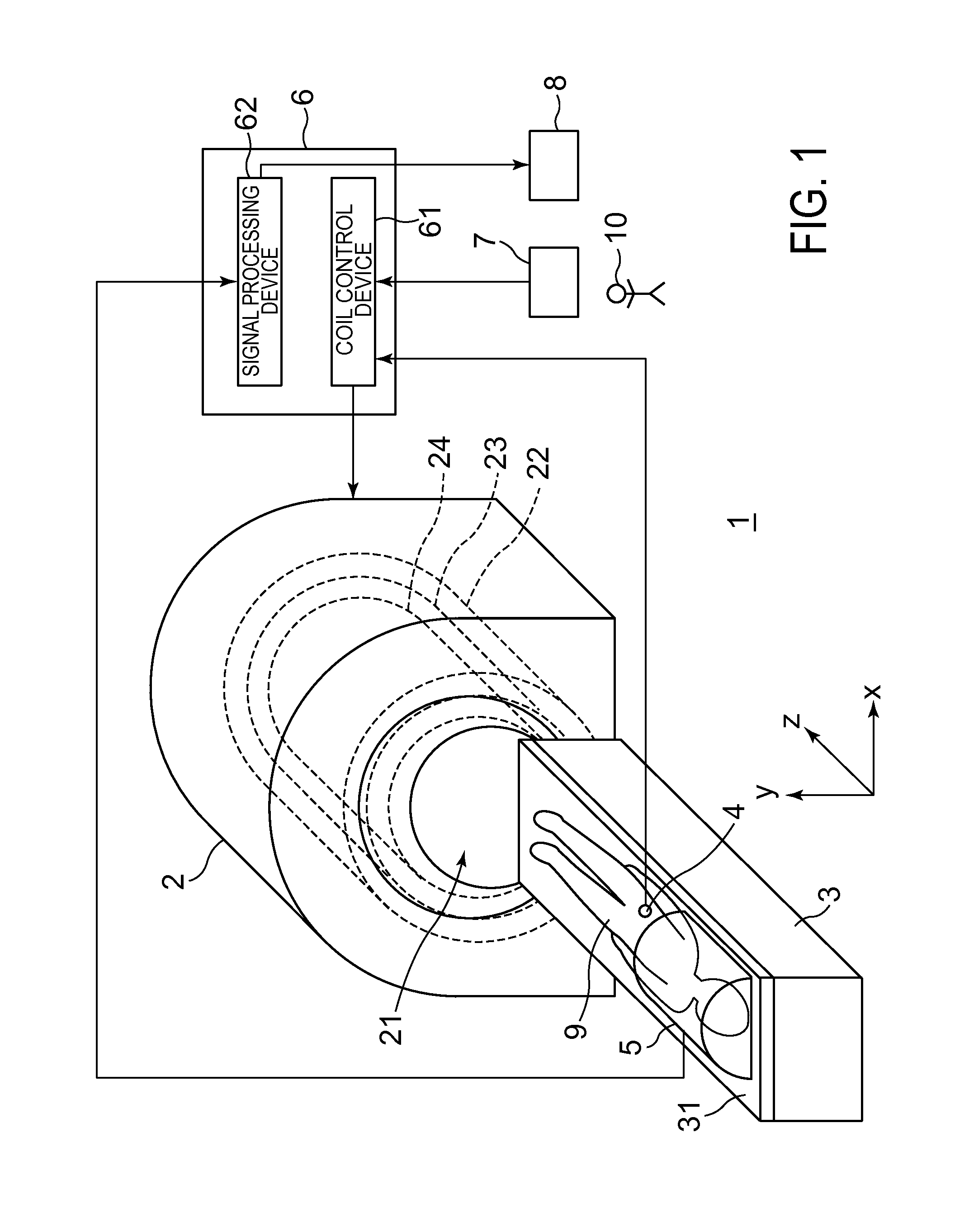
[0042]FIG. 1 is a schematic diagram of a magnetic resonance imaging apparatus 1 according to one embodiment of the invention.

[0043]The magnetic resonance imaging apparatus (hereinafter called “MRI (Magnetic Resonance Imaging) system”) 1 has a coil assembly 2, a table 3, a heartbeat sensor 4, a receiving coil 5, a controller 6, an input device 7 and a display device 8.

[0044]The coil assembly 2 has a bore 21 in which a subject 9 is accommodated, a superconductive coil 22, a gradient coil 23 and a transmitting coil 24. The superconductive coil 22 applies a static magnetic field BO, the gradient coil 23 applies a gradient pulse and the transmitting coil 24 transmits an RF pulse.

[0045]The table 3 has a cradle 31. The cradle 31 is configured so as to move in a z direction and a −z direction. With the movement of the cradle 31 in the z direction, the subjec...


PUM


Abstract

A magnetic resonance imaging apparatus includes a gradient coil for applying a gradient pulse, a transmitting coil for transmitting an RF pulse, and a coil control device for controlling the gradient coil and the transmitting coil in such a manner that a pulse sequence for (A) making an absolute value of longitudinal magnetization of a first background tissue and an absolute value of longitudinal magnetization of a second background tissue longer in T1 value than the first background tissue smaller than an absolute value of longitudinal magnetization of body fluid of a subject, (B) acquiring magnetic resonance signals from the subject, and (C) flipping transverse magnetization of the second background tissue to longitudinal magnetization is repeatedly executed.

Description

CROSS REFERENCE TO RELATED APPLICATIONS[0001]This application claims the benefit of Japanese Patent Application No. 2009-020787 filed Jan. 30, 2009, which is hereby incorporated by reference in its entirety.BACKGROUND OF THE INVENTION[0002]The embodiments described herein relate to a magnetic resonance imaging apparatus for imaging a subject and a program therefore.BACKGROUND ART[0003]As a method for visualizing arterial blood of the head of a subject, there has been known MRA (Magnetic Resonance Angiography) for visualizing a blood flow of a subject without using a contrast agent. As one example of MRA, there has been known, for example, a Time-SLIP method (refer to Mitsue Miyazaki and six more inventors “Recent Development of Non-Contrast-Enhanced MRAngiography”, Image Information Medical, Sangyo Kaihatsukiko Inc., September Issue, 2006, p. 952-957).[0004]Since it becomes hard to visually identify arterial blood when background tissues (such as fat and cerebrospinal fluid) are vis...

Claims


Application Information

Patent Timeline
Patent Type & Authority Applications(United States)
IPC IPC(8): A61B5/055
CPCA61B5/0263A61B5/0456A61B5/0555G01R33/5635G01R33/5602G01R33/5607A61B5/7285A61B5/352A61B5/055
Inventor TAKEI, NAOYUKI
Owner GE MEDICAL SYST GLOBAL TECH CO LLC
Why Eureka
Try Eureka