Device and method for spinous process distraction

a technology of spinous process and device, applied in the field of spinous process distraction, can solve the problems of increasing the trauma of the procedure, the failure to correct the latero-lateral alignment of the device, and the non-trivial deployment of the element via a dorsal-angled approach

Active Publication Date: 2010-08-05
SEASPINE
View PDF29 Cites 72 Cited by
  • Summary
  • Abstract
  • Description
  • Claims
  • Application Information

AI Technical Summary

Benefits of technology

[0010]According to a further feature of the present invention, a distal portion of the implant body is formed with a set of lateral projections configured for inhibiting withdrawal of the distal portion between adjacent spinous processes after deployment.
[0011]According to a further feature of the present invention, the lateral projections provide barbed ridges shaped to inhibit withdrawal of the distal portion between adjacent spinous processes after deployment.
[0014]According to a further feature of the present invention, the at least one elongated retention feature is a barbed ridge shaped to inhibit withdrawal of the distal portion between adjacent spinous processes after deployment.

Problems solved by technology

Although the above documents refer to minimally invasive techniques for implanting the devices disclosed, the deployment of the element in a latero-lateral direction via a dorsal-angled approach is non-trivial, requiring sizable incisions and manipulation within the body to achieve the required deployment of an implant.
In some cases, spinous process distraction devices necessitate bilateral access during implantation, thereby necessarily increasing trauma from the procedure compared to a unilateral approach.
On the other hand, attempts to implement a unilateral approach device would present more complex obstacles regarding the correct latero-lateral alignment of the device.

Method used


Image

  • Device and method for spinous process distraction
  • Device and method for spinous process distraction
  • Device and method for spinous process distraction

Examples


Embodiment Construction

[0036]The present invention is an implant, a system for implantation, and a corresponding method, for maintaining a minimum inter-spinous-process spacing.

[0037]The principles and operation of implants, systems and methods according to the present invention may be better understood with reference to the drawings and the accompanying description.

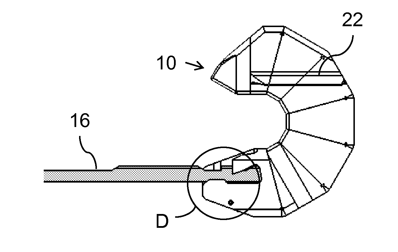
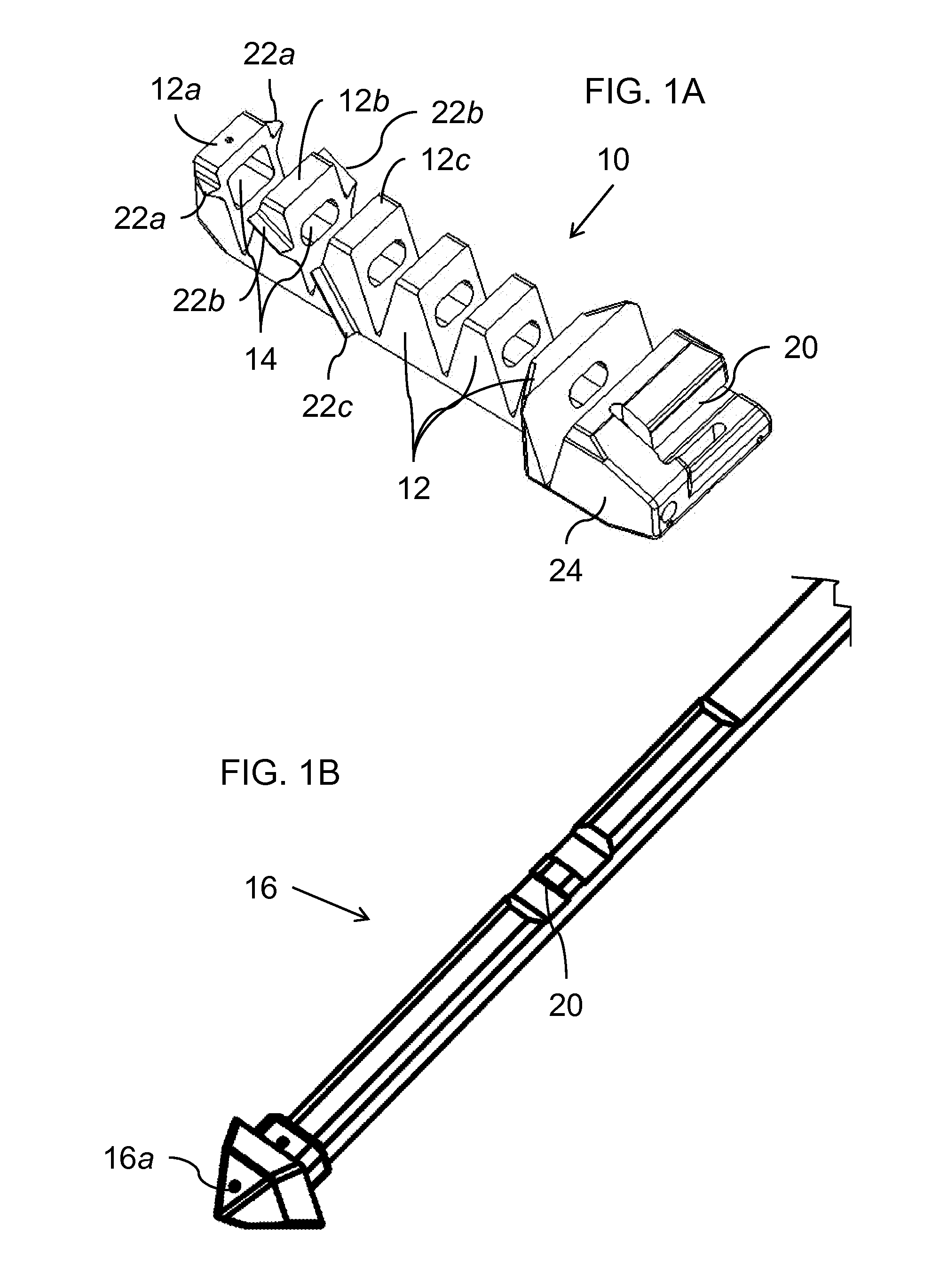
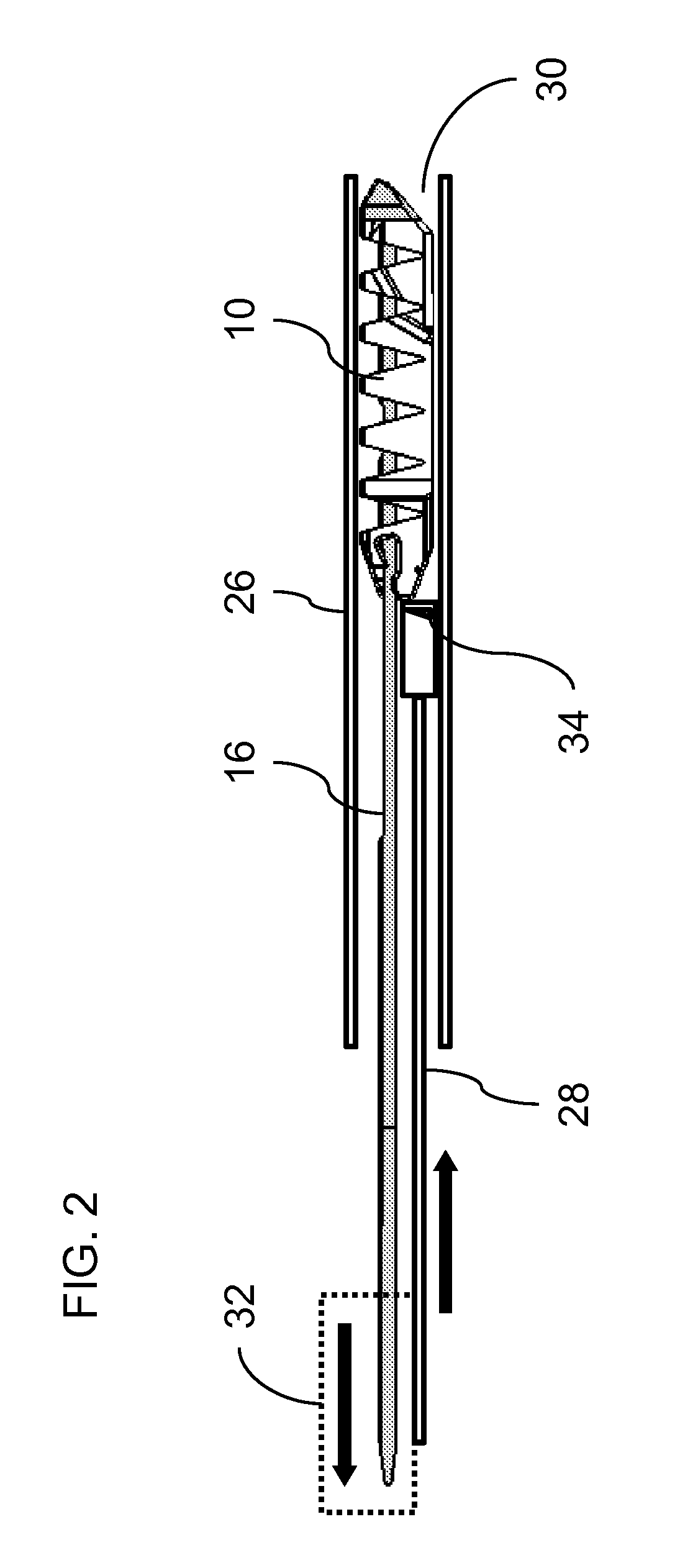
[0038]Referring now to the drawings, FIGS. 1A-7B show various parts of an implant, a corresponding delivery system, and the corresponding manner of deployment of the implant, constructed and operative according to the teachings of the present invention, for maintaining a given minimum inter-spinous-process spacing between adjacent spinous processes of a human or animal subject.

[0039]Generally speaking, the implant is formed from an implant body 10 including a plurality of segments 12 hingedly interconnected so as to assume a straightened state (FIGS. 2, 3A and 4A) for delivery along a conduit and a curved deployed state (FIGS. 3C, 4C and 5). A...


PUM


Abstract

An implant for maintaining a given minimum inter-spinous-process spacing includes an implant body with a number of segments hingedly interconnected so as to assume a straightened state for delivery along a conduit and a curved deployed state. An elongated tightening element is anchored at the distal segment of the implant body and passes along a channel extending along the implant body. Tension applied to the tightening element biases the implant body from the straightened state to the curved deployed state. Preferably, when the tightening element is deflected to reach the curved deployed state, a locking arrangement locks the tightening element relative to the implant body, thereby retaining the implant in the curved deployed state. A distal portion of the implant body is preferably formed with a set of lateral projections to inhibit withdrawal of the distal portion between adjacent spinous processes after deployment.

Description

FIELD AND BACKGROUND OF THE INVENTION[0001]The present invention relates to spinous process distraction and, in particular, it concerns a device and method for minimally invasive deployment to achieve spinous process distraction.[0002]Various devices have been proposed for distraction between adjacent spinous processes, or more precisely, to prevent extension at one or more level between adjacent vertebrae in order to treat various spinal conditions. Examples of such devices are described in U.S. Pat. No. 6,152,926, U.S. Pat. No. 6,695,842, US2004 / 0153071 and WO03007791 which may be referred to for further background to the physiological aspects of the present invention.[0003]Although the above documents refer to minimally invasive techniques for implanting the devices disclosed, the deployment of the element in a latero-lateral direction via a dorsal-angled approach is non-trivial, requiring sizable incisions and manipulation within the body to achieve the required deployment of an...

Claims


Application Information

Patent Timeline
Patent Type & Authority Applications(United States)
IPC IPC(8): A61B17/88A61B17/70A61B17/56
CPCA61B17/7065
Inventor SIEGAL, TZONYELISHA, YINNON
Owner SEASPINE
Why Eureka
Try Eureka