PLC having communication function

Inactive Publication Date: 2010-08-05
KOYO ELECTRONICS INDS
View PDF4 Cites 7 Cited by
  • Summary
  • Abstract
  • Description
  • Claims
  • Application Information

AI Technical Summary

Benefits of technology

[0017]According to the networking PLC core, network PLC and network PLC system provided by the present invention, the conventional problems concerning the adoption of variously different serial communications and networks and the creation of any complicated large-volume program can be solved, costs and working steps for building a PLC system can be largely reduced, any type of PLC system ranging from a micro PLC system comprising a single network PLC to a mid-size or large-scale PLC system comprising plural network PLCs and plural network devices such as motion control, temperature control and sensor drive can be flexibly and easily built, and maintenance and repair operations can be simplified, which improves the reliability of the system.

Problems solved by technology

In the conventional network-based PLC system, the PLCs on the network merely operate to transfer data, and it is not possible to functionally distinguish one PLC from other PLCs.
Further, it is difficult to perform the peer-to-peer data communication between the devices of each PLC control within the network.
It is difficult to share PLC commands and data information (hereinafter, referred to as PLC information) between PLCs within the network, and it is not possible for one PLC to control other PLCs.
Therefore, when PLCs themselves are improved and have advanced features, an application program related to the PLCs becomes complicated, and a large capacity is required, resulting in an increase in manufacturing and development costs and troubles.

Method used


Image

  • PLC having communication function
  • PLC having communication function
  • PLC having communication function

Examples


Embodiment Construction

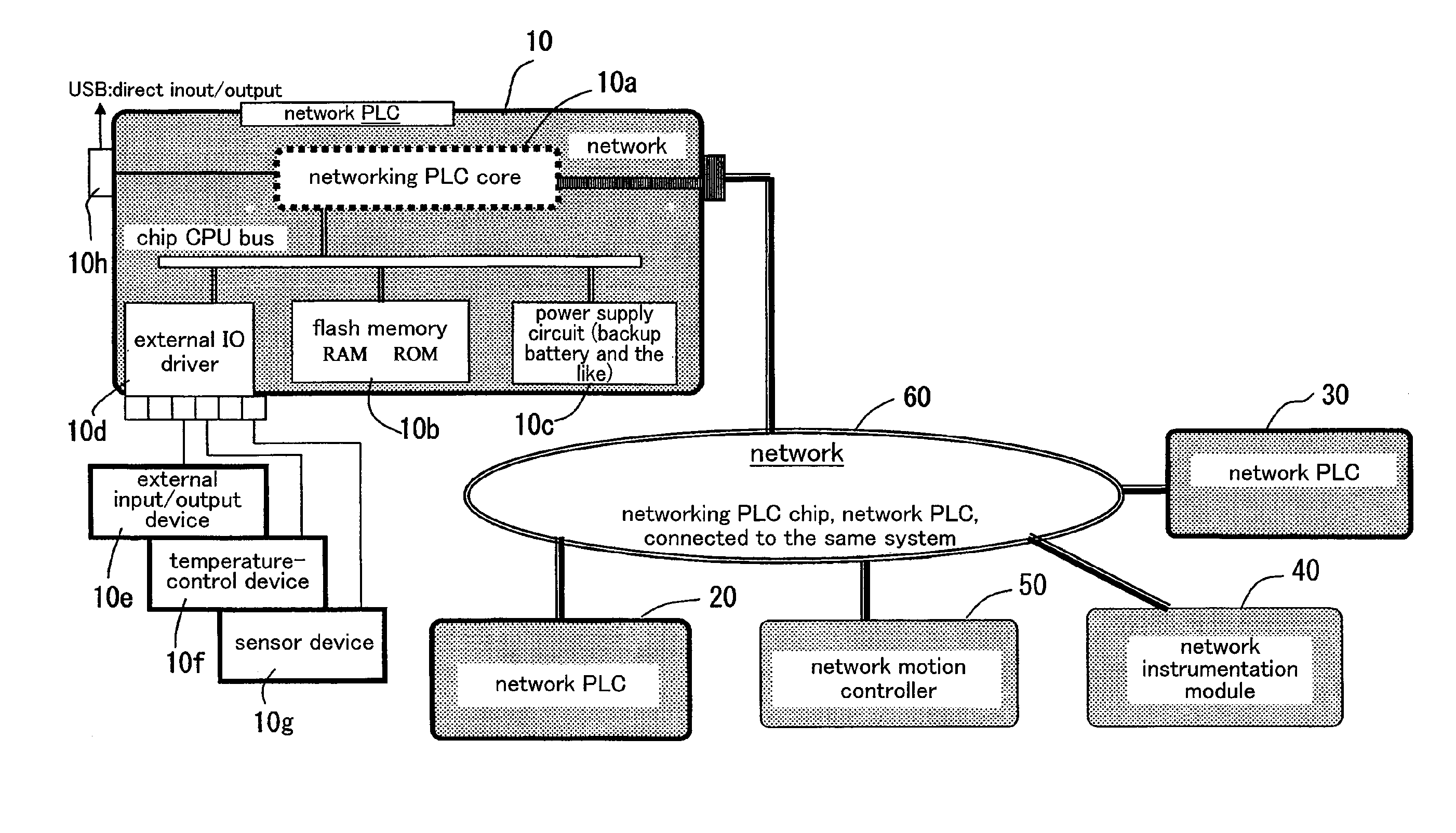
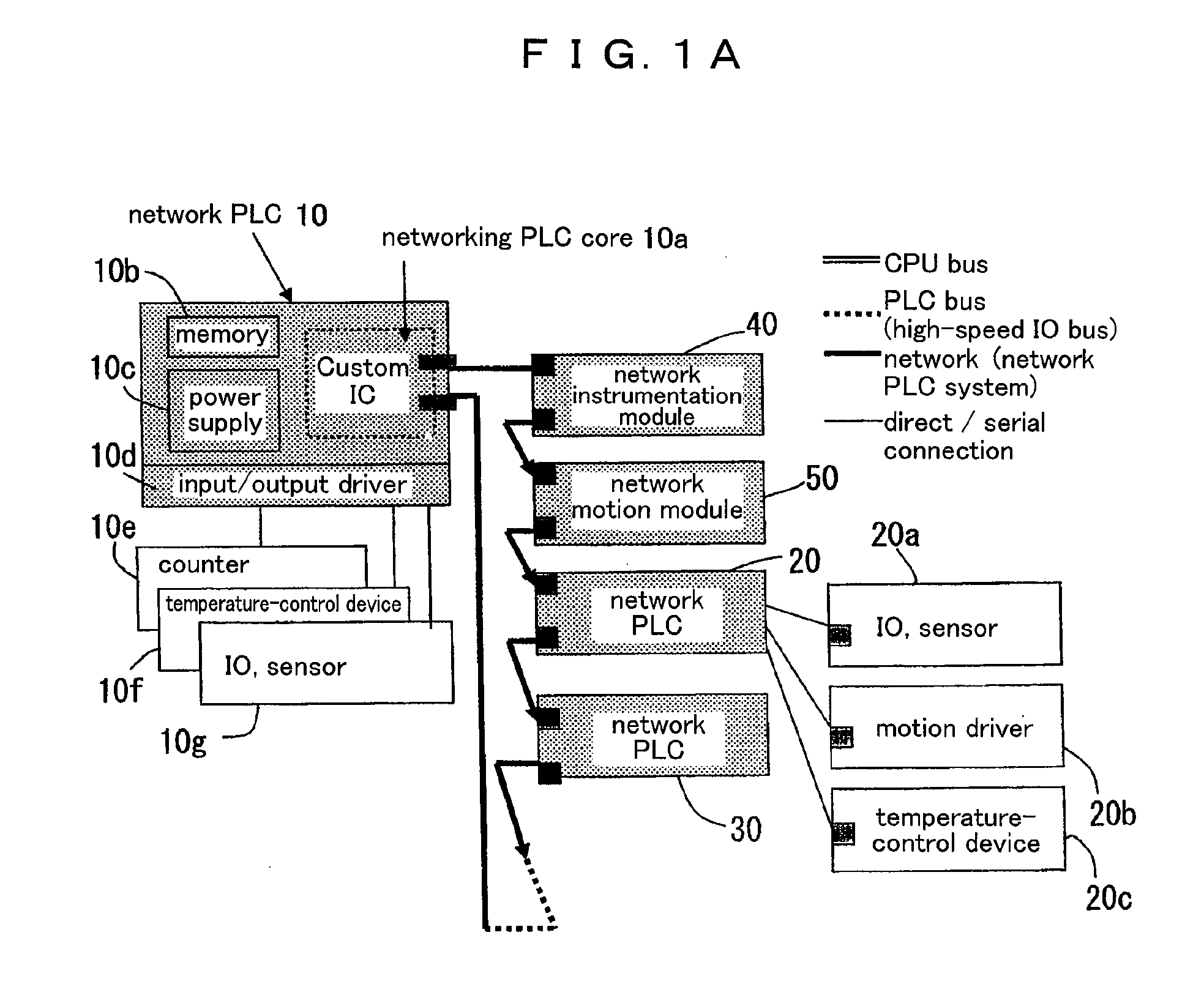
[0033]A simple description of a network PLC system according to the present invention is given below in comparison to a conventional PLC system in which multiple CPU modules are adopted. The network PLC system according to the present invention is illustrated in FIG. 1A, while the conventional PLC system having a multi-CPU modular configuration.

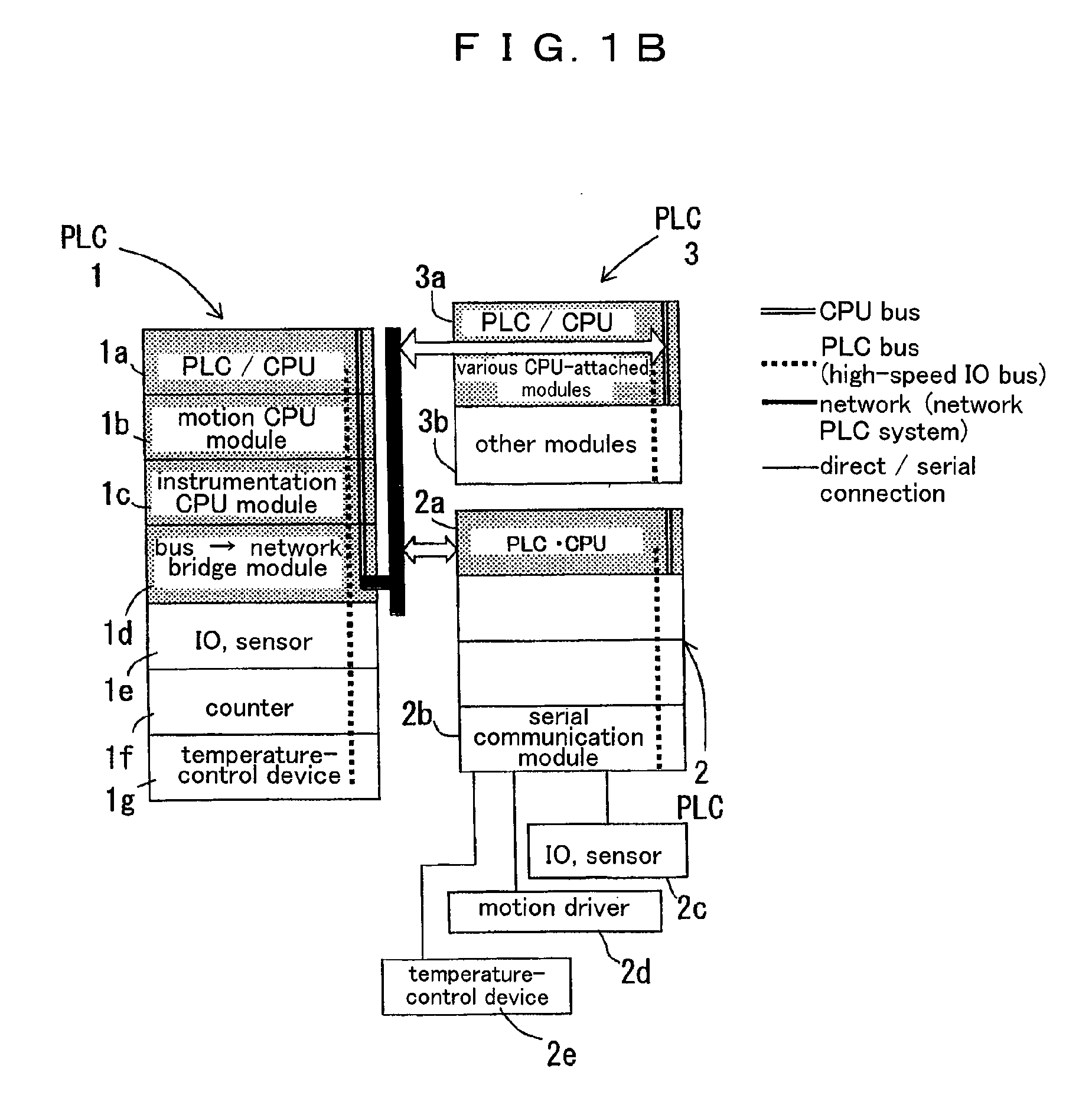
[0034]FIG. 1B is an illustration of an example in which three PLCs having a multiprocessor modular configuration are connected to one another through a network or serial communication, thereby constituting a sophisticated mid-size or large-scale PLC system.

[0035]A PLC 1 comprises plural CPU-embedded modules 1a-1d connected to one another by a CPU bus, and plural modules 1e-1g connected to a PLC bus.

[0036]A PLC 2 comprises a CPU-embedded module 2a and external devices 2c-2e by way of a serial communication module 2b, and is connected to the modules 2c-2e through the serial communication.

[0037]A PLC 3 comprises plural CPU-embedded modules 3a an...


PUM


Abstract

A networking PLC core comprising a program for uniting a programmable logic controller function to a fourth transport layer and a fifth session layer in compliance with network communication specifications in an OSI reference network model embedded therein, and a single or plural ICs or modules for exclusive use which are configured to store, manage and execute the program.

Description

FIELD OF THE INVENTION[0001]The present invention relates to a PLC system for connecting plural PLCs and devices through communication or a network in the technical field relevant to PLC (programmable logic controller) used to control machines and devices, an assembling plant, and the like.BACKGROUND OF THE INVENTION[0002]For a current PLC system, there are many different-sized PLCs, such as micro PLC, compact PLC and mid-size PLC, in response to the size and functions of a required control mode. The type of serial communication and network adopted for connection also varies from one company to another. In the conventional network-based PLC system, the PLCs on the network merely operate to transfer data, and it is not possible to functionally distinguish one PLC from other PLCs. Further, it is difficult to perform the peer-to-peer data communication between the devices of each PLC control within the network. It is difficult to share PLC commands and data information (hereinafter, re...

Claims


Application Information

Patent Timeline
IPC IPC(8): G06F13/14G06F17/30
CPCG05B19/052G05B2219/15125G05B2219/1208
Inventor YUINE, TSUTOMUMATSUMOTO, SHIGEHARU
Owner KOYO ELECTRONICS INDS
Why Eureka
Try Eureka