Frame-less, Split Pipe Wiper

a wiper and split-pipe technology, applied in the field of apparatus, can solve the problems of mud clinging to the exterior of the pipe or tubing, affecting the cleaning effect, polluting the environment, etc., and achieve the effect of simple, convenient installation and robust design

Inactive Publication Date: 2010-08-12
REDDOCH SR JEFFREY A
View PDF3 Cites 3 Cited by
  • Summary
  • Abstract
  • Description
  • Claims
  • Application Information

AI Technical Summary

Benefits of technology

[0011]This invention discloses a mechanized pipe wiper that utilizes a pair of opposing wiper elements, one of which is slidably disposed in a pair channels formed in the other. The wiper elements are moved toward (“closed”) and apart from (“opened”) each other by only two air cylinders. When closed the wiper elements surround the exterior of the pipe or tubing When opened the wiper elements allowed for the pipe or tubing to be rotated or large items to be run through the pipe wiper. By removal two pins, one attaching each air cylinder, the pipe wiper can be split into two “halves” which can be easily installed around pipe in the hole.
[0012]The disclosed invention utilizes the fixed actuator assembly to hold the base of the air cylinders and contains a channel in which the sliding actuator assembly is slidably disposed, eliminating the need for a surrounding frame. Also, because of the simple, robust design of the disclosed invention, a housing is also not needed. The disclosed invention can be installed and removed, either for installation or maintenance, from the work-floor of the drilling rig simply by putting it through the opening created by removal of the master bushing from the rotary table of the work-floor.

Problems solved by technology

In many cases the mud contains ingredients which are hazardous to personnel and constitute environmental pollutants, is viscous and tends to cling to pipe or tubing being pulled from the earth-bore.
When pulling pipe or tubing from the hole, mud clinging to the exterior of the pipe or tubing presents a problem.
If allowed to fall on the work-floor of the drill rig can present a slip hazard.
If allowed to remain on the pipe or tubing as it is lifted and / or stored vertically in the derrick can, particularly in windy weather blow off the pipe and injure the eyes of skin or personnel or blow off of the drilling rig and pollute the environment.
In addition thereto mud which is allowed to fall on the floor of the rig, where it must be washed from, not only consumes unnecessary time and labor but the mud become diluted, may no longer be usable, constitute a disposal problem and require new mud to be purchased.
There are, however, certain limitations to use of a donut pipe-wiper.
If the donut is cut radially installation is facilitated but then the donut cannot grip the pipe tightly.
If on the other hand the donut is not cut, then installation on the pipe is difficult.
In either case, drilling mud is usually abrasive and tends to rapidly enlarge the hole of the donut, making it less effective or require replacement.
Because of these, and other problems, associated with donut-like pipe wipers it is not uncommon to see drilling rigs running with loose, ineffective donut wipers or running without any form of pipe wiper.
While pipe-wipers of the “surrounding framework” design were generally effective wiping pipe there were certain disadvantages attendant to their usage.
Pipe wipers of said design are typically large, heavy, bulky, complex and expensive.
They were typically too large to install from the work-floor of the drilling rig (through the opening in the work-floor created by removal of the master bushing from the rotary table of the work-floor).
On the other hand they were difficult, if not impossible, to install from the side in the limited amount of space between the bottom of the work-floor and the pollution pan (“drip pan”) of the drilling rig.
Due to this type of pipe wipers utilization of a surrounding framework they could not be installed with pipe suspended from the work-floor of the drilling rig.
If this type of wiper became worn or damaged they were difficult to access, remove, repair and install a repaired or new unit.
Because of these limitations it is not uncommon to see drilling rigs running with ineffective, inoperative pipe wipers of this type of design or being operated without any form of pipe wiper.

Method used


Image

  • Frame-less, Split Pipe Wiper
  • Frame-less, Split Pipe Wiper
  • Frame-less, Split Pipe Wiper

Examples


Embodiment Construction

[0028]While the present invention will be described with reference to preferred embodiments, it will be understood by those who are skilled in the art that various changes may be made and equivalents may be substituted for elements thereof without departing from the scope of the invention. In addition, many modifications may be made to adapt a particular situation or material to the teachings of the invention without departing from the essential scope thereof. It is therefore intended that the present invention not be limited to the particular embodiments disclosed as the best mode contemplated for carrying out this invention, but that the invention will include all embodiments and legal equivalents thereof.

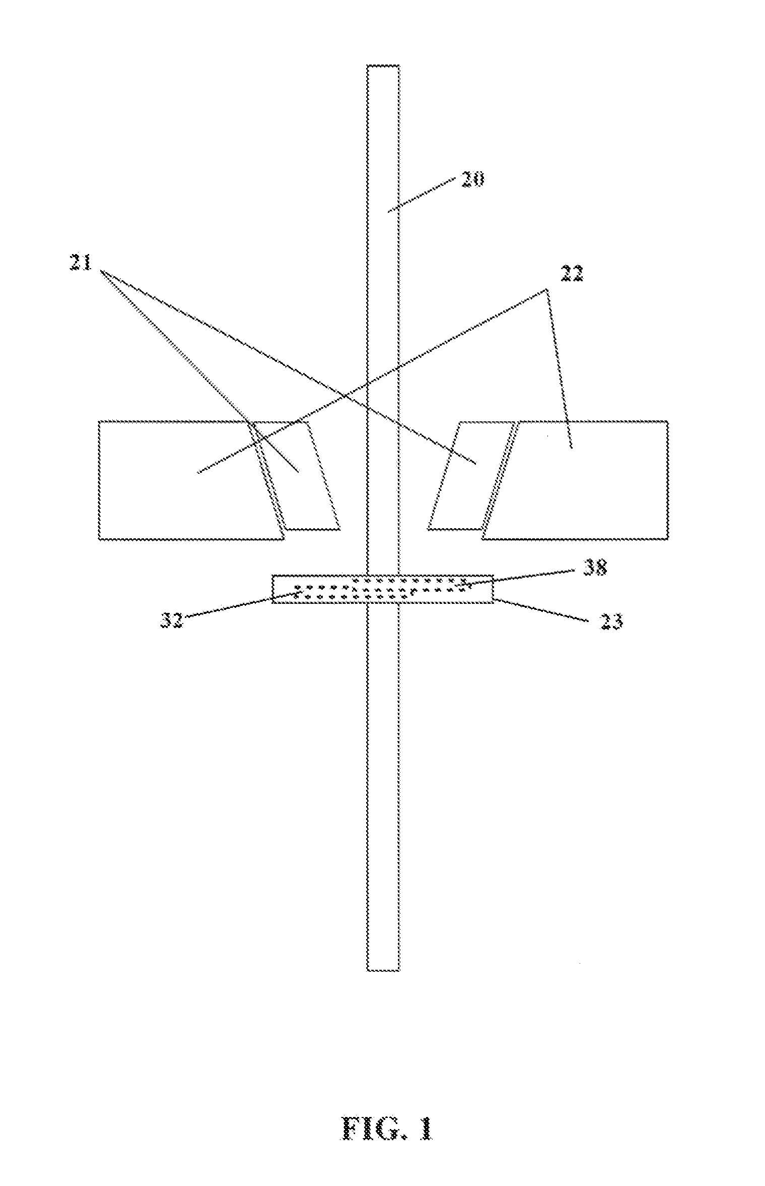
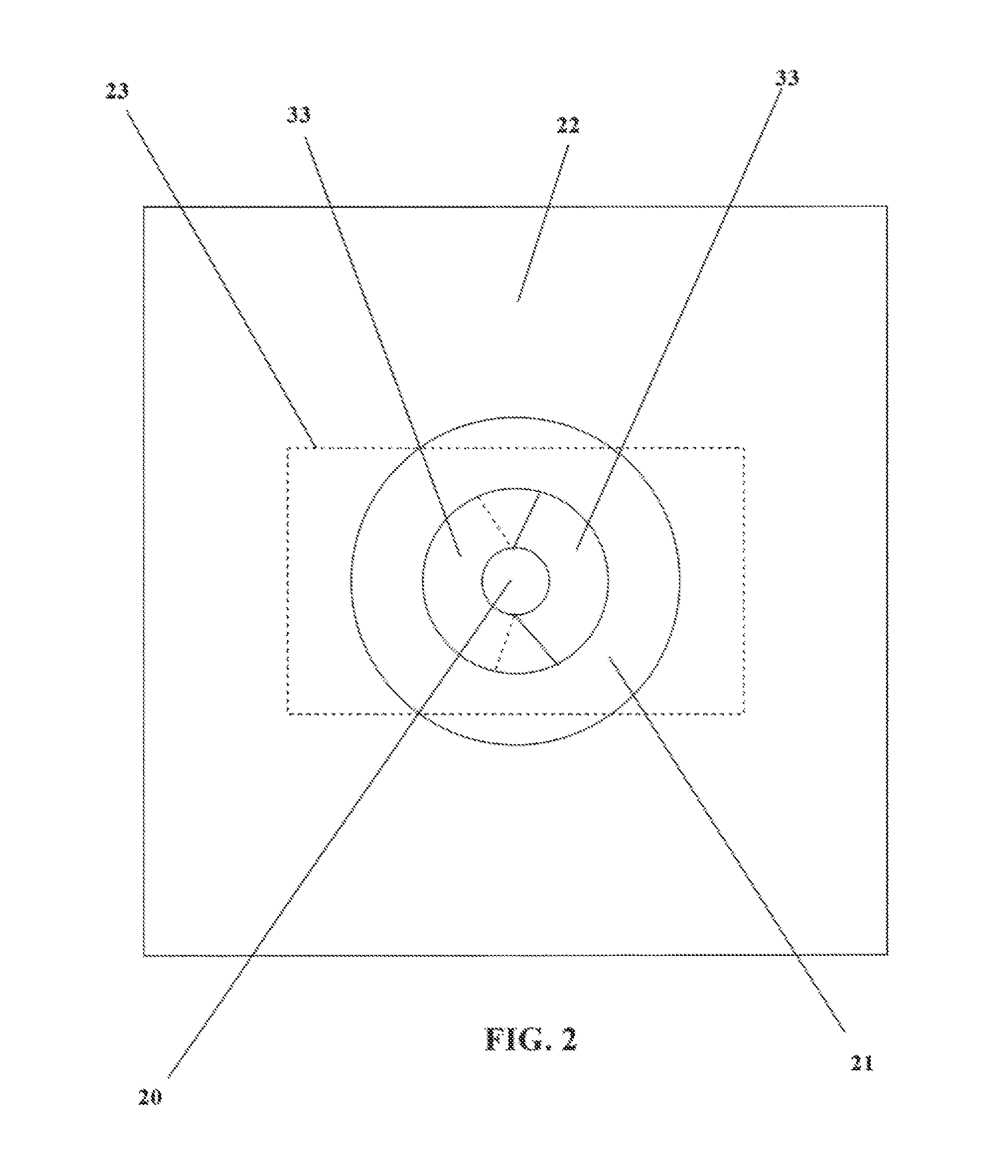
[0029]Looking at FIG. 1, drill pipe (20) is being wiped as it is pulled from the hole through the rotary table (22) and master bushings / slips (21) while the disclosed invention (23) disposed below rotary table (22) and is stripping and wiping the mud (25) from the exterior of dri...


PUM


Abstract

The frame-less, split pipe disclosed herein includes a fixed actuator assembly with carries a blade-like pipe wiper element and a sliding actuator assembly which carries a similar blade-like pipe wiper element. Each of the pipe wiper elements is disposed between a clamp and the base of their respective actuator assemblies. The sliding actuator assembly is disposed in a pair of channels disposed above the claim of the fixed actuator assembly. A pair of pneumatic cylinders, one on each side of the fixed actuator assembly moves the sliding actuator assembly between open and closed positions. For installation, removal or maintenance on a pipe wiper it may be split into two open-throated components by removing the pins which attach the operating rods of the pneumatic cylinders to clevises of the sliding actuator assembly.

Description

CROSS REFERENCE TO RELATED APPLICATIONS[0001]This application claims priority based on U.S. Provisional Patent Application No. 61 / 150,709 filed Feb. 2, 2009.1. FIELD OF THE INVENTION[0002]The invention disclosed and claimed herein relates to apparatus (commonly called a “pipe wiper”) for stripping excess drilling fluid (commonly called “drilling mud” or simply “mud”) from the exterior of pipe or tubing (commonly called “drill string”) used to drill and / or complete earth-bores (“hole” or “well”) as said pipe or tubing is being removed (“pulled”) from the earth-bore (“hole” or “well”).2. GENERAL BACKGROUND[0003]During drilling or completion of an earth-bore (“hole” or “well”) some form of drilling fluid (“mud”) is typically used for a variety of reasons, to lubricate and cool the drill bit, to circulate drill cuttings to the surface, provide a fluid pressure to keep the well from blowing out and other reasons. In many cases the mud contains ingredients which are hazardous to personnel...

Claims


Application Information

Patent Timeline
Patent Type & Authority Applications(United States)
IPC IPC(8): E21B37/00
CPCE21B33/08
Inventor REDDOCH, SR., JEFFREY A.
Owner REDDOCH SR JEFFREY A
Why Eureka
Try Eureka