Drawer type cooking device

Active Publication Date: 2010-08-12
SHARP KK
View PDF18 Cites 9 Cited by
  • Summary
  • Abstract
  • Description
  • Claims
  • Application Information

AI Technical Summary

Benefits of technology

[0023]According to the drawer type cooking device, the set depth size of the farthest portion can be reduced by combining the arrangements, positions and orientations of the high pressure transformer and the cooling fan which are included in the various electric components disposed at the farthest portion of the cooking device for activating the device. By reducing the depth size of the farthest portion of the device, the front surface of the door can be made flush with the front panel of the cabinet without sacrificing the opening size of the door being drawn out, and there is no longer any need for a special ceiling structure for storing the electric cord for power supply on the ceiling.
[0024]According to the present drawer type cooking device, it is preferable to dispose the cooling fan laterally, and to position the high pressure transformer in the opened space below the cooling fan. By positioning the cooling fan laterally, a space is formed below the fan, and the high pressure transformer can be stored efficiently using the formed space.
[0025]According to the drawer type cooking device of the present invention, the device can be built into the walls of kitchen cabinets having a standardized size, and the front side of the door can be made flush with the front panel of the cabinet, so that a superior interior design having completely-flat built-in equipment can be realized.
[0026]The power supply cable can be suspended in the course of the construction process, according to which the workability is improved. There is no need to form a power cable storage portion to the cooking device body, so that the weight and cost of the cooking device body can be reduced.

Problems solved by technology

According to this type of storing method of the power supply cord 4, the power cord may easily be sandwiched in the gap between the farthest portion of the cooking device body 1 and the kitchen cabinet 5, which may lead to damage of the cord.
On the other hand, built-in cooking devices are allowed to take in and discharge air only by way of limited square inches that could be spared apparently on the front surface, posing design challenges toward specialists in the trade to decide upon cooking device configurations.
According to the above-mentioned air blow path, the cross-sectional area of the air blow path was varied greatly, so that it was difficult to increase the air blow volume, and since the arrangement caused great pressure loss, there was great air blow loss and the air blow efficiency of the cooling fan 56a was deteriorated.
Therefore, it is a challenge to further reduce the depth of the cooking device, correct the irrational air blow path and thereby improve the air blow efficiency of the cooling fan 56a.
Further, regarding the trend of interior designs, kitchens composed of built-in equipment having no protruded portions are highly evaluated, but according to the prior art drawer type cooking device, it was impossible to form the front door of the device to be flush with the front panel of the cabinet since the rear portion of the casing constituting the cooking device body was supported at the back of the cabinet, so that the door portion was protruded from the front panel of the cabinet.
Therefore, there were cases where even if the functions of the cooking device were highly evaluated, the device was not adopted in fitted kitchens or designed kitchens since the design thereof did not match the interior design of the kitchens.
As described, the most important design challenge in this field of art is to have full knowledge of the size of the heating chamber desired by the user, and to ensure the minimum allowable heating chamber size.

Method used


Image

  • Drawer type cooking device
  • Drawer type cooking device
  • Drawer type cooking device

Examples


Embodiment Construction

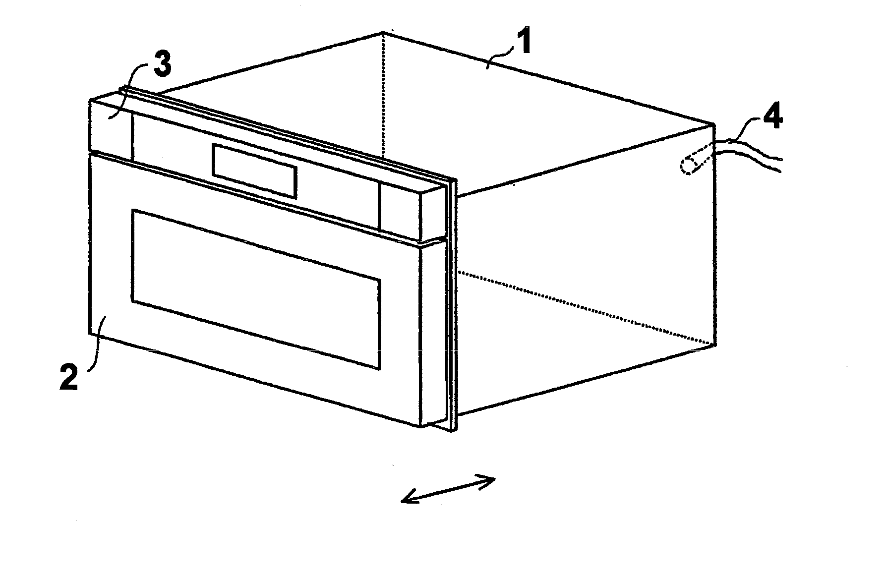
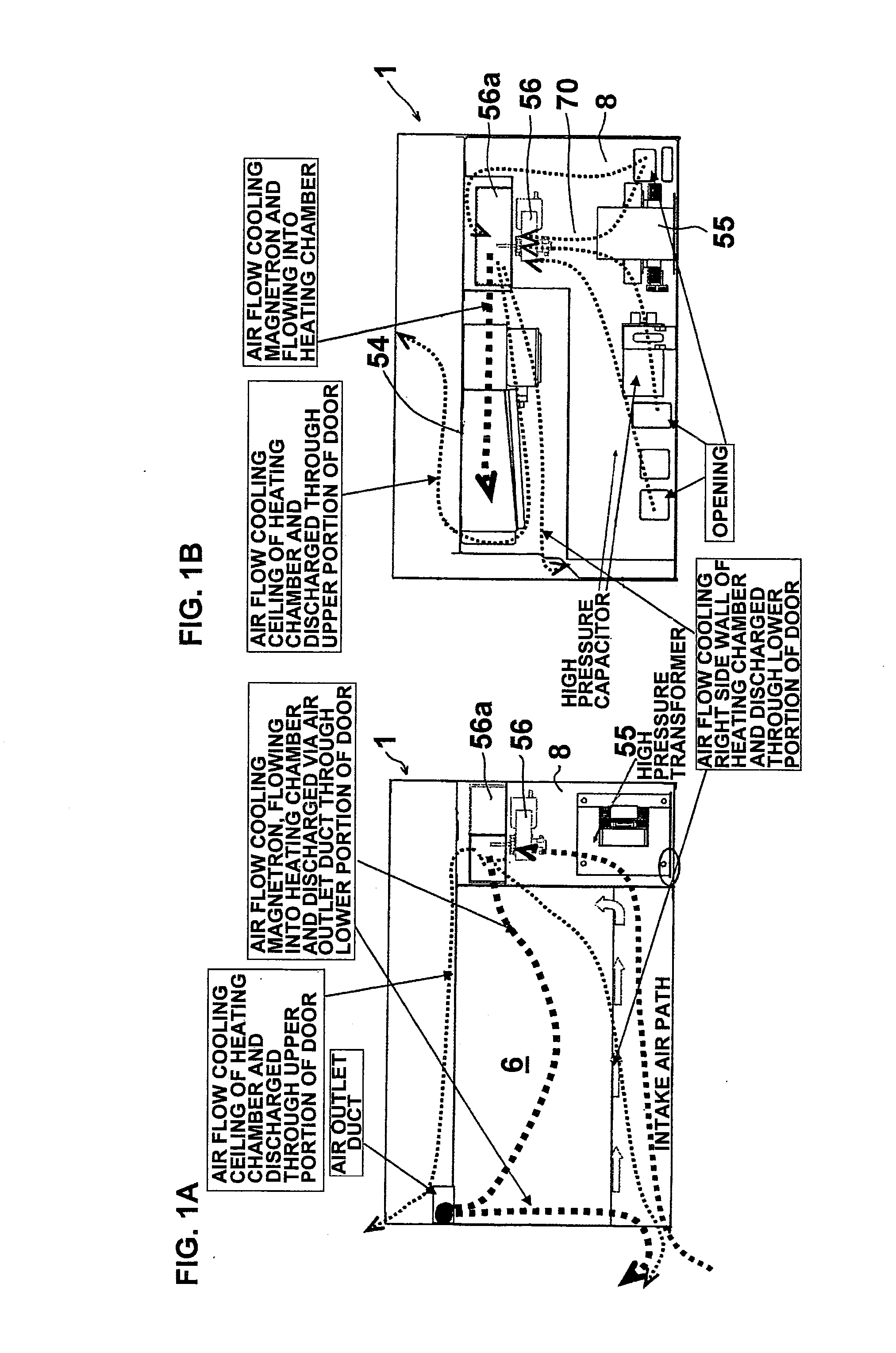
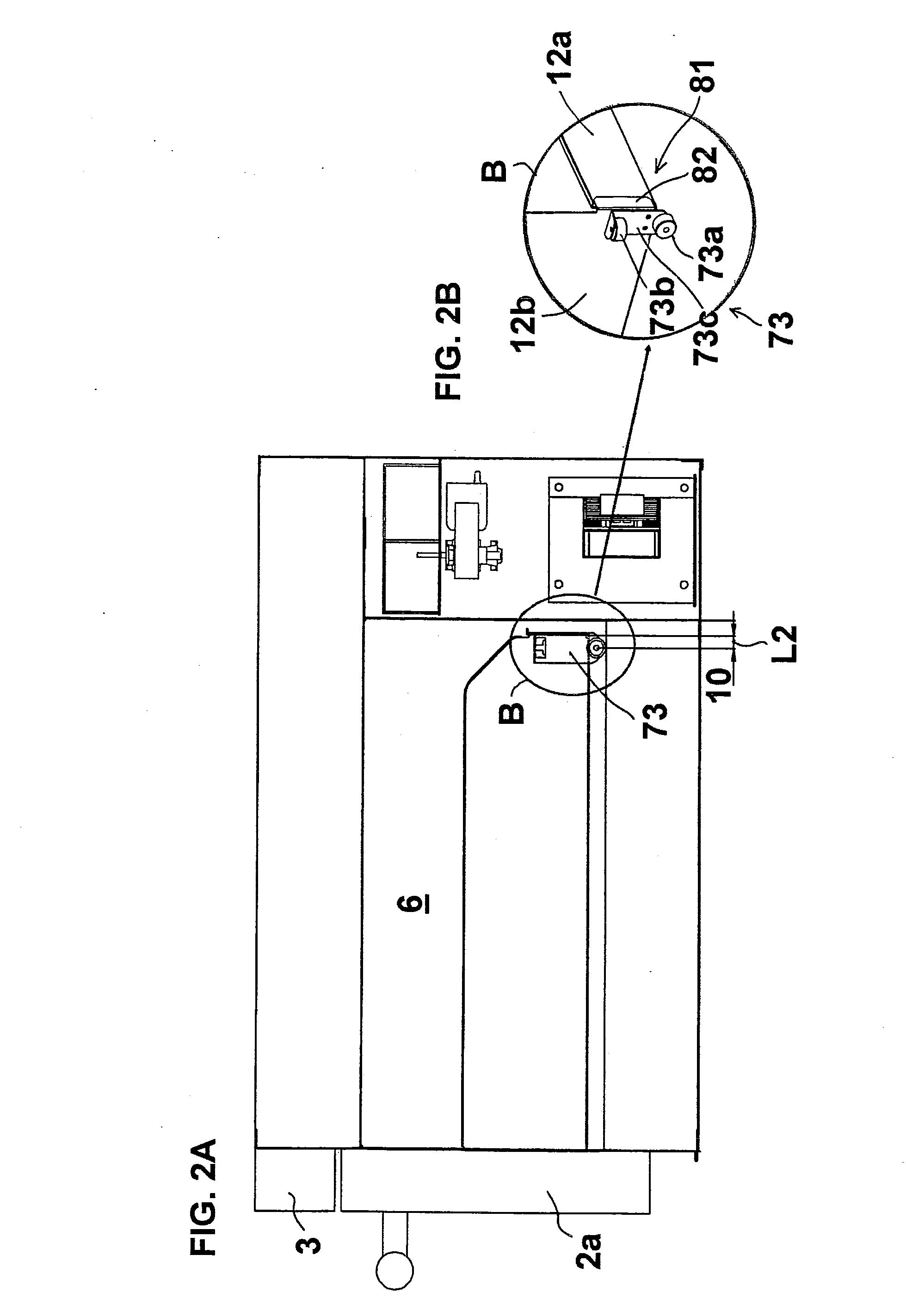
[0041]Now, the preferred embodiments of the drawer type cooking device according to the present invention will be described with reference to the drawings. One example of the drawer type cooking device according to the present invention applied to a built-in cooking equipment is illustrated in FIGS. 1A and 1B. The basic structure of the drawer type cooking device are equivalent to those of the prior art drawer type cooking device, so the components are denoted by the same reference numbers and the detailed descriptions thereof are omitted. FIG. 1A is a right side view and FIG. 1B is a rear side view showing a rear side chamber according to one embodiment where the drawer type cooking device is applied to a built-in kitchen equipment. In the rear view, the back wall 5c is removed.

[0042]A rear wall (back panel) 1a of the heating chamber is extended in four directions and acts as a partition wall with respect to the back area. A farthest portion 8 of the cooking device is formed at the...


PUM


Abstract

The invention provides a drawer type cooking device having a cooling fan 56a disposed laterally, so that a space 70 is formed below the cooling fan 56a, enabling a high pressure transformer 55 to be disposed efficiently using this space 70. By the combination of the arrangement, position and orientation of the cooling fan, it becomes possible to reduce the set depth size at the farthest portion of the cooking device body 1. By reducing the depth size, the front surface of a cabinet and the front surface of a door 2 can be disposed flush with each other, without having to sacrifice the depth of the heating chamber 6.

Description

[0001]The present application is based on and claims priority of Japanese patent application No. 2009-026637 filed on Feb. 6, 2009, the entire contents of which are hereby incorporated by reference.BACKGROUND OF THE INVENTION[0002]1. Field of the Invention[0003]The present invention relates to a cooking device in general, and more specifically, to a drawer type cooking device in which a drawer body storing an object to be heated is capable of being drawn out from within a cooking device body.[0004]2. Description of the Related Art[0005]Cooking devices having a drawer body formed integrally with a door capable of being drawn out to the front side of the cooking device have been proposed. Since such drawer type cooking devices can be built into the space below the countertop of kitchens, the cooking devices can be installed without occupying the space above the countertop used for preparation of cooking or for the actual cooking, they are suitably adopted in kitchen arrangements where...

Claims


Application Information

Patent Timeline
IPC IPC(8): A21B1/22A23B4/03
CPCF24C15/006F24C15/162
Inventor YOSHIDOME, AKIHIRO
Owner SHARP KK
Why Eureka
Try Eureka