
Motorcycle radar detection system

a radar detection and motorcycle technology, applied in the direction of communication jamming, measurement devices, instruments, etc., can solve the problems of not being able to isolate road noise, difficult to adapt radar detectors and their components for motorcycle use, etc., to achieve convenient and effective use of motorcycles

Active Publication Date: 2010-08-12
RETAILDNA +1
View PDF27 Cites 9 Cited by
  • Summary
  • Abstract
  • Description
  • Claims
  • Application Information

AI Technical Summary

Benefits of technology

[0011]It is an object of the present invention to provide a radar detection system that can conveniently and effectively be used with a motorcycle.
[0013]In another embodiment of the present invention, a mounting assembly is provided to secure the main console to a portion of the motorcycle, and a quick-release mechanism is incorporated on the main console and the mounting assembly to allow the main console to be quickly and easily secured to and removed from a support bracket of the mounting assembly.

Problems solved by technology

Unfortunately, it is more challenging to adapt radar detectors and their components for use with motorcycles.
First, noise is a major problem, because the road noise cannot be insulated or blocked out.
Wind and engine noises also pose similar problems.
As a result, the motorcycle rider cannot hear audible alerts issued by the radar detector.
Second, the rider often cannot see visual alerts being emitted by the radar detector because the radar detector is often mounted at a location that is outside the rider's visual field.
In addition, motorcycles also receive more direct sunlight than automobiles, and the direct sunlight can make it difficult for the rider to see the displays on the radar detector.
Third, riders often wear gloves when riding.
The buttons on conventional radar detectors are small, so they are difficult to actuate when wearing gloves.
Fourth, mounting a radar detector and its components to a motorcycle can be challenging because one must find a location on a motorcycle that provides a good fit, is visually appealing, and does not interfere with the rider's operation of the motorcycle.
Fifth, waterproofing can also be a problem.
Conventional automobile radar detectors are not waterproof, and are therefore not well suited for use with motorcycles.

Method used


Image

  • Motorcycle radar detection system
  • Motorcycle radar detection system
  • Motorcycle radar detection system

Examples


Embodiment Construction

[0032]The following detailed description is of the best presently contemplated modes of carrying out the invention. This description is not to be taken in a limiting sense, but is made merely for the purpose of illustrating general principles of embodiments of the invention. The scope of the invention is best defined by the appended claims.

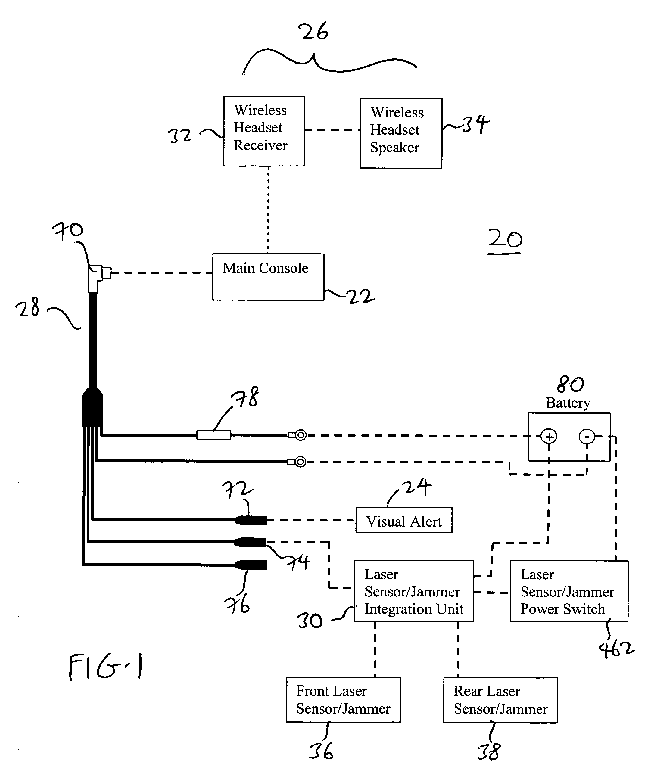
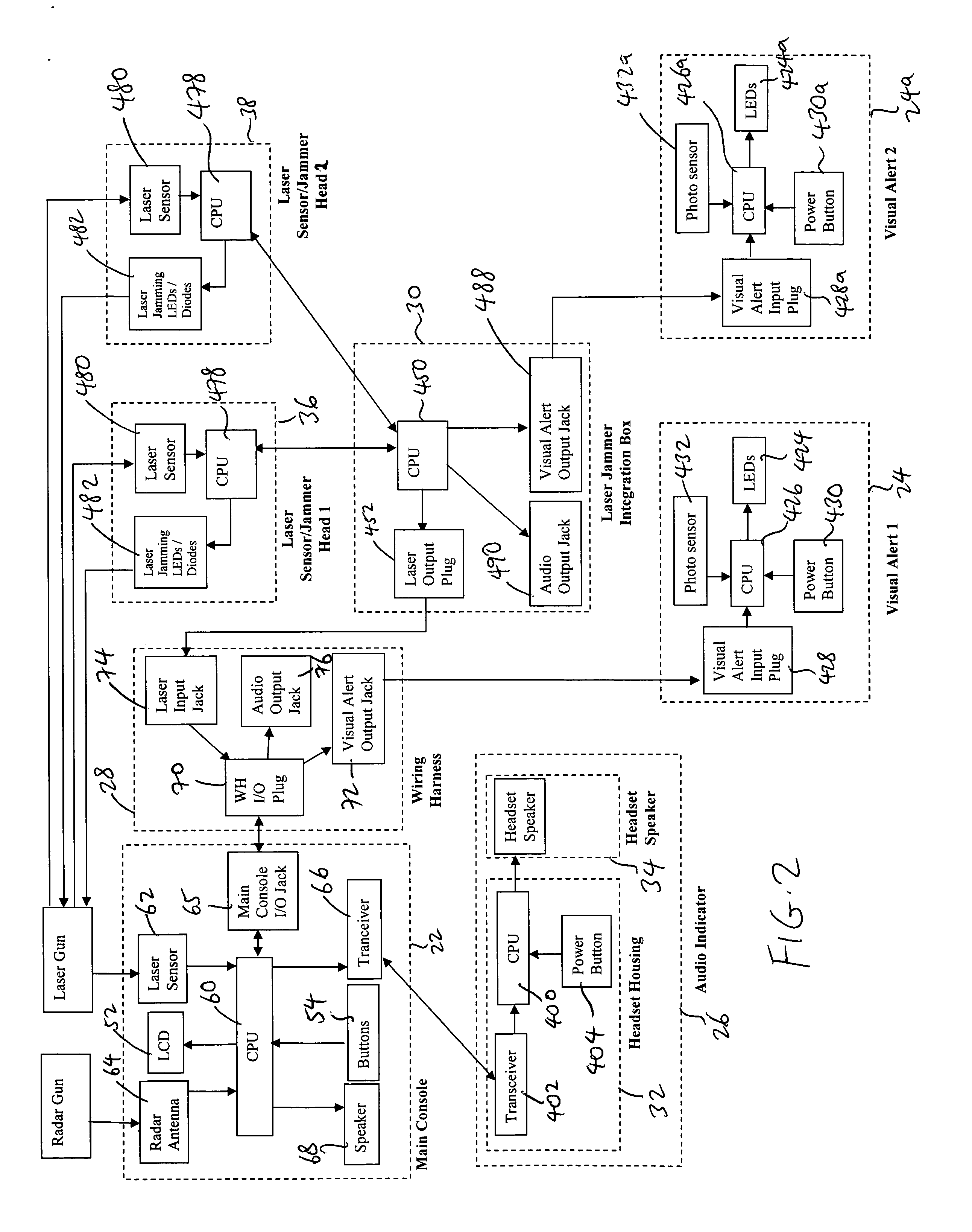
[0033]FIGS. 1-2 illustrate one embodiment of a radar detection system 20 according to the present invention. The system 20 includes a main console 22, a visual alert 24, an audio indicator 26, a wiring harness 28, and a laser sensor / jammer assembly. The audio indicator 26 includes a receiver module 32 and a speaker 34. The laser sensor / jammer assembly includes an integration unit 30, a front laser sensor / jammer head 36 and a rear laser sensor / jammer head 38.

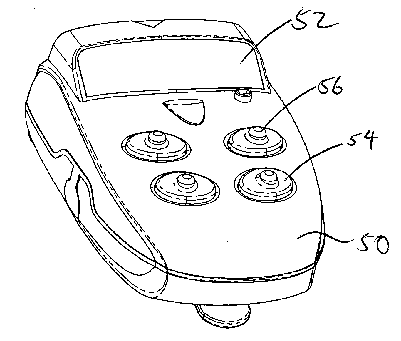
[0034]The main console 22 operates in the same manner as a conventional automobile radar detector. Referring to FIGS. 2-6, the main console 22 has a housing 50 (which can be made of two housing...


PUM


Abstract

A radar detection system for use with a motorcycle includes a main console that includes a single I / O interface, a detector and a controller that transmits an alert signal upon the detection of a radar or laser by the detector. The radar detection system also includes a visual alert that receives the alert signal from the main console, and a display which provides a visual display of the alert signal, with the visual alert being mounted to a portion of a motorcycle. The radar detection system further includes a wiring harness having a plurality of I / O interfaces, including a first I / O interface that is removably coupled to the single I / O interface of the main console, and a second I / O interface that is removably coupled to the visual alert.

Description

INCORPORATION BY REFERENCE[0001]This application is related to application Ser. No. 11 / 707,476, filed Feb. 16, 2007, whose entire disclosure is incorporated by this reference as though set forth fully herein.BACKGROUND OF THE INVENTION[0002]1. Field of the Invention[0003]The present invention relates to a motorcycle radar detection system.[0004]2. Description of the Prior Art[0005]Most radar detectors are designed for use inside or with automobiles. Unfortunately, it is more challenging to adapt radar detectors and their components for use with motorcycles.[0006]First, noise is a major problem, because the road noise cannot be insulated or blocked out. Wind and engine noises also pose similar problems. As a result, the motorcycle rider cannot hear audible alerts issued by the radar detector.[0007]Second, the rider often cannot see visual alerts being emitted by the radar detector because the radar detector is often mounted at a location that is outside the rider's visual field. In a...

Claims


Application Information

Patent Timeline
IPC IPC(8): G01S7/42G01S7/38
CPCG01S7/022G01S7/495G01S7/4804G01S7/38
Inventor CHEN, WAYNEGOLD, ADAM
Owner RETAILDNA
Learn More