Gear pump

a gear pump and gear technology, applied in the direction of machines/engines, rotary/oscillating piston pump components, liquid fuel engines, etc., can solve the problems of fluid leakage from the gear pump, gap formation insufficient prevention of the positional deviation between the body and the housing, so as to prevent the fluid pressure in the gear pump and maintain the pump efficiency of the gear pump. , the effect of increasing the frictional for

Inactive Publication Date: 2010-08-12
KYB CORP
View PDF1 Cites 8 Cited by
  • Summary
  • Abstract
  • Description
  • Claims
  • Application Information

AI Technical Summary

Benefits of technology

[0009]According to this invention, a number of particles are interposed between the end surface of the body and the end surface of the housing, thereby increasing a frictional force generated in a joint portion between the body and the housing such that positional deviation generated between the body and the housing by a fluid pressure in the gear pump can be prevented effectively, and as a result, a pump efficiency of the gear pump can be maintained.

Problems solved by technology

However, when a cutting depth of the processing teeth engraved in the end surface of the body is small, positional deviation between the body and the housing cannot be prevented sufficiently.
On the other hand, when the cutting depth of the processing teeth is large, a gap may be formed between the body and the housing, and as a result, fluid may leak from the gear pump.

Method used


Image

  • Gear pump
  • Gear pump
  • Gear pump

Examples


Embodiment Construction

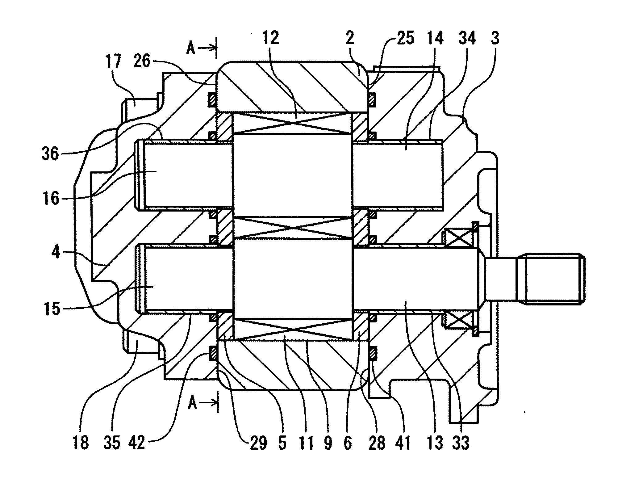
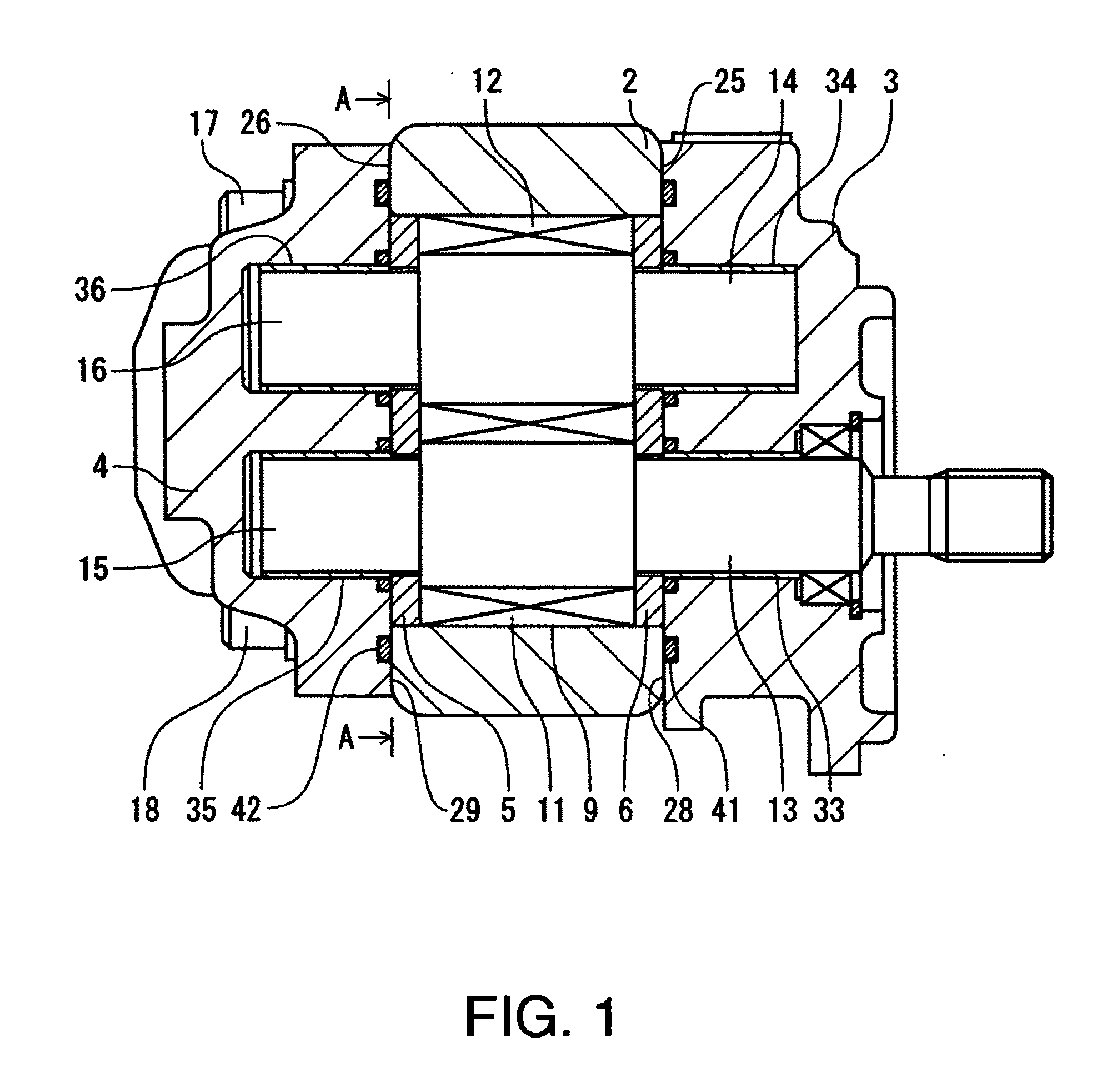
[0012]An embodiment of this invention will be described below with reference to the figures.

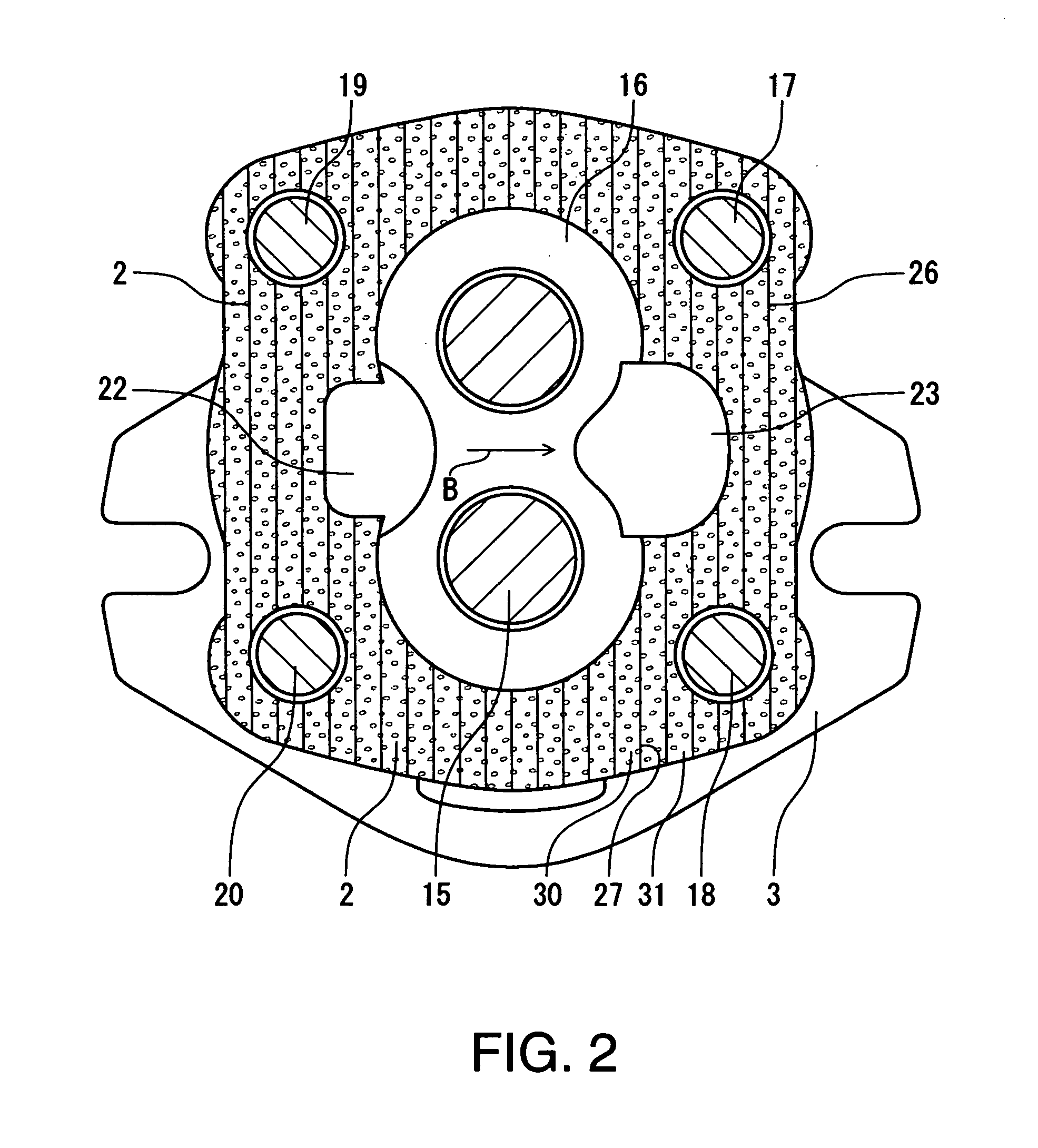
[0013]As shown in FIG. 1, a gear pump 1 comprises a body 2 into which a drive gear 11 and a driven gear 12 are incorporated as a pair of gears, and housings 3, 4 that contact the body 2 from either side. Side plates 5, 6 are interposed between respective end faces of the drive gear 11 and driven gear 12 and the housings 3, 4.

[0014]A gear chamber 9 that houses the drive gear 11 and driven gear 12 is provided on an inner side of the body 2, and the housings 3, 4 contact respective end surfaces 25, 26 of the body 2.

[0015]The housing 3 includes an end surface 28 that contacts the end surface 25 of the body 2 so as to close one end of the body 2 and function as a mounting flange attached to a support member, not shown in the figure.

[0016]A seal ring 41 is interposed between the end surface 25 of the body 2 and the housing 3, and the gear chamber 9 is sealed by the seal ring 41.

[0017]It should be n...


PUM


Abstract

A gear pump (1) that discharges a fluid by rotating while a pair of gears (11, 12) are intermeshed includes a body (2) into which the respective gears (11, 12) are incorporated, a housing (3, 4) that contacts the body (2), a number of particles (30) that are interposed between an end surface (25, 26) of the body (2) and an end surface (28, 29) of the housing (3, 4), which contact each other, to prevent positional deviation between the body (2) and the housing (3, 4), and a fastening member (17 to 20) that fastens the housing (3, 4) to the body (2).

Description

TECHNICAL FIELD[0001]This invention relates to a gear pump that discharges a fluid by rotating while a pair of gears are intermeshed.BACKGROUND ART[0002]A gear pump provided in an oil pressure device, a water pressure device, and so on includes a body into which a pair of gears is incorporated and a housing that contacts the body. The body and the housing are fastened to each other by a plurality of bolts.[0003]During an operation of the gear pump, a force that attempts to move the housing in a single direction relative to the body is generated by fluid pressure generated in the body.[0004]JP6-147133A discloses a conventional gear pump in which processing teeth are formed on an end surface of the body which contacts the housing. When the body and the housing are fastened to each other by the plurality of bolts, rib-shaped processing teeth engraved in the end surface of the body dig into the end surface of the housing, thereby preventing positional deviation between the body and the ...

Claims


Application Information

Patent Timeline
Patent Type & Authority Applications(United States)
IPC IPC(8): F01C1/18
CPCF01C21/10F01C21/102F01C21/104F04C2/12F04C2/18F04C2270/70F04C15/0026F04C2230/60F04C2240/10F04C2240/30F04C14/28
Inventor SHIMAMURA, TATEYUKI
Owner KYB CORP
Why Eureka
Try Eureka