
System and Method for Performing Signaling on Behalf of a Stateless Client

a stateless client and signaling system technology, applied in the field of communication systems, can solve the problems of high computational power requirement placed on these endpoints, complex protocol and procedure signaling methods, and relatively high-powered and expensive computer processors

Inactive Publication Date: 2010-08-12
CISCO TECH INC
View PDF18 Cites 1 Cited by
  • Summary
  • Abstract
  • Description
  • Claims
  • Application Information

AI Technical Summary

Benefits of technology

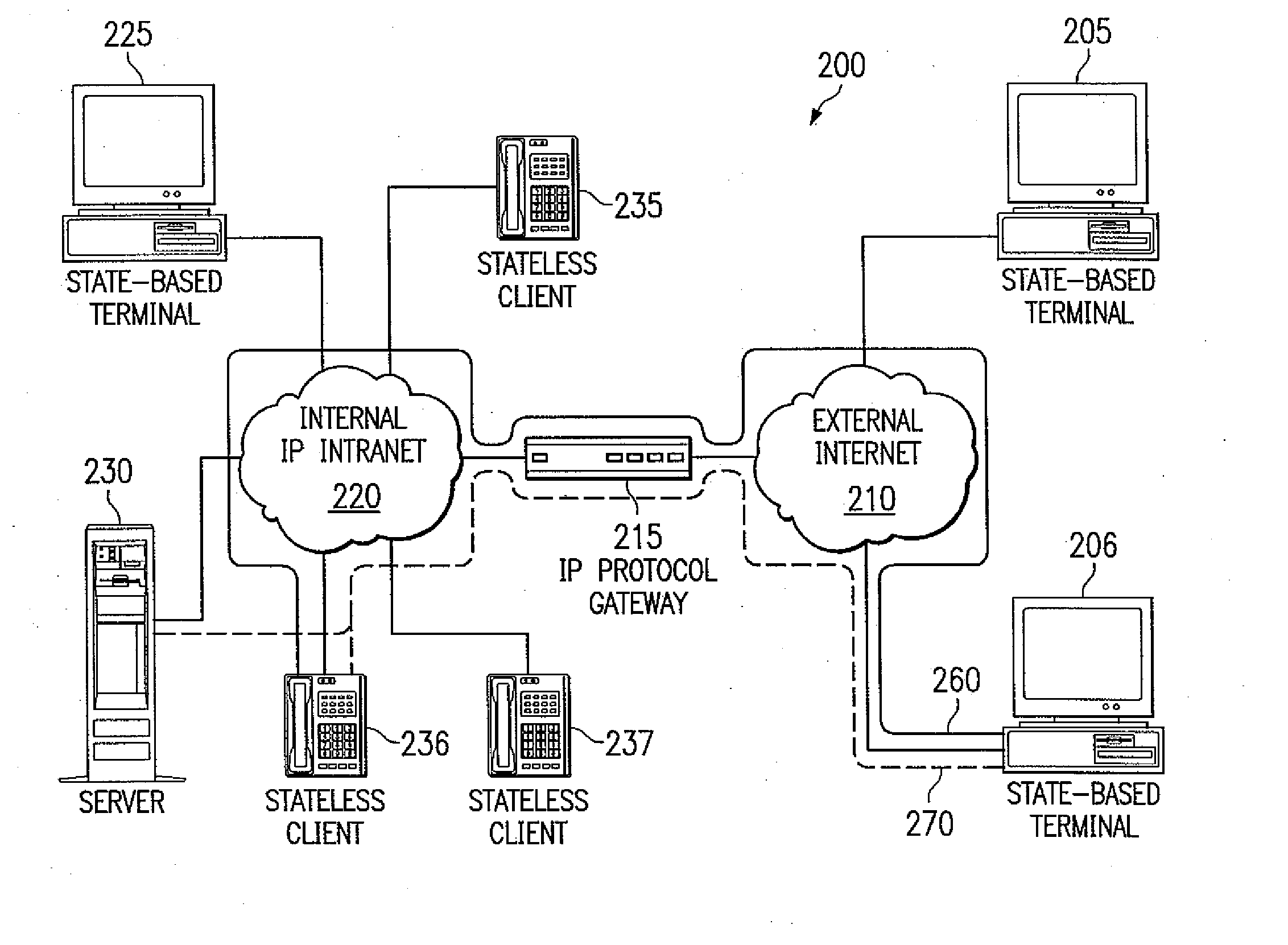
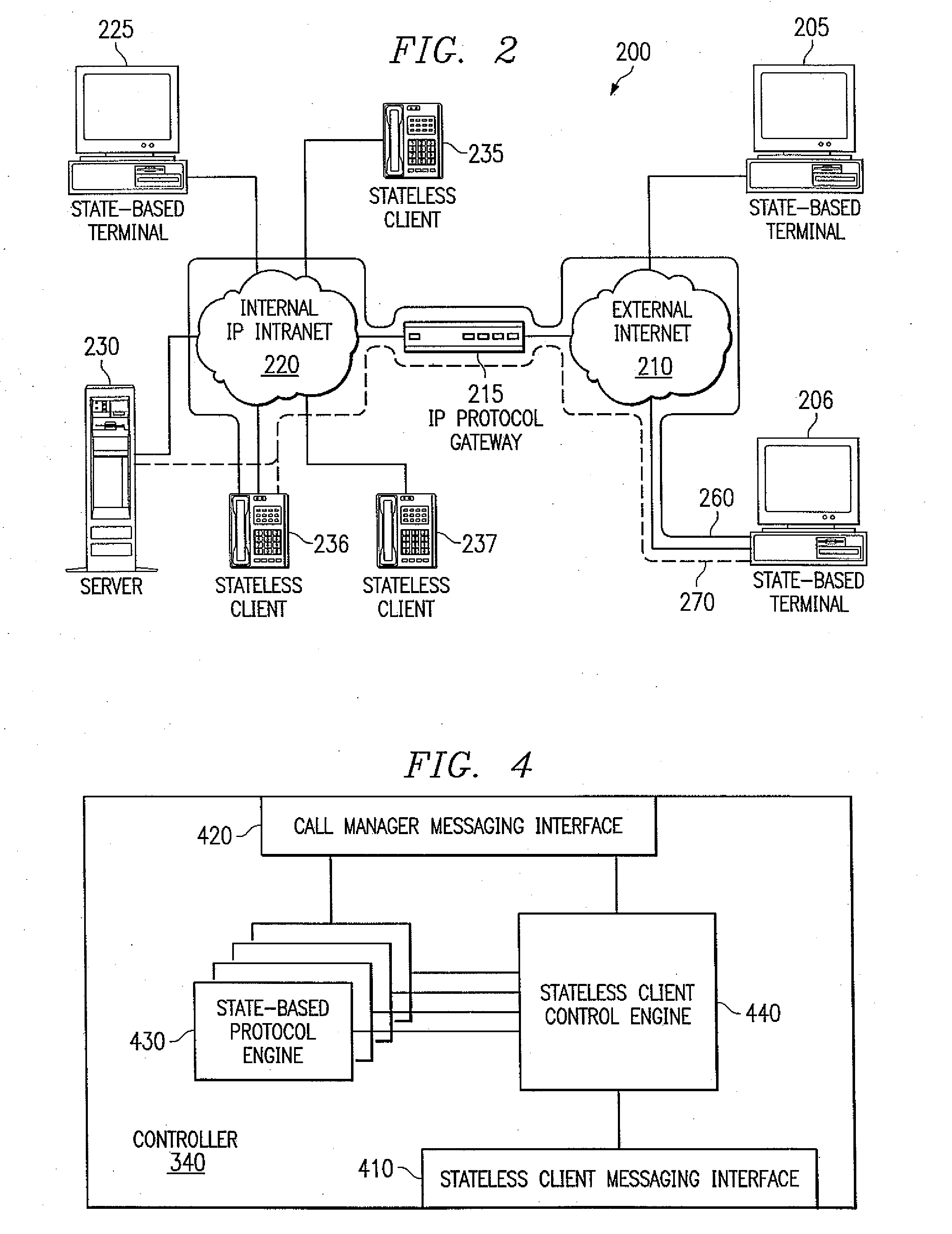
[0011]To address the above-discussed deficiencies of the prior art, the present invention provides a system for, and method of, performing state-based signaling on behalf of a stateless client. In one embodiment, the system includes a controller, couplable to a state-based terminal, that translates at least one stateless signaling message received from the stateless client to at least one state-based signaling message for presentation to the state-based terminal thereby facilitating a media stream communications session between the stateless client and the state-based terminal over an Internet Protocol (IP)-based network. In a related, but alternative embodiment of the present invention, the controller translates at least one state-based signaling message received from the state-based terminal to at least one stateless signaling message for presentation to the stateless client.
[0012]The present invention introduces the broad concept of a controller that performs state-based signaling on behalf of a stateless client device to facilitate a communications session therewith. For the purposes of the present invention, a stateless client is a low capabilities device that is incapable of performing state-based signaling. In essence, it is a “dumb” terminal. In contrast, the state-based terminal is a higher capabilities device that is capable of performing state-based signaling. In essence, the state-based terminal is a complex terminal such as a multimedia personal computer. The present invention recognizes that in many environments it is advantageous to employ a low capabilities client and provide a controller to perform signaling functions therefor.

Problems solved by technology

Due to the complexity of these specifications, a significant computational power requirement is placed upon these endpoints.
These current standards-based, protocol and procedure signaling methods may be described as complex.
If the endpoints are not computer-based workstations, however, processing the state-based protocols typically dictates the inclusion of a relatively high-powered and expensive computer processor in combination with a dedicated device, known as a low-capability client.
Employing intelligence such as a processor with the low-capability client increases both the cost and design complexity as well as the requirements to meet other constraints on the system such as radiated emissions or temperature environments.
As the ITU-T Recommendation H.323 and related recommendations evolve, a higher and higher burden will be placed upon the low-capability clients such that they may remain interoperable with other computer-based workstations.
As a consequence, the fundamental issues associated with deploying telephony over IP networks include difficulty in adapting to and supporting new and changing signaling methods at client devices, particularly as the number of clients increases.
Additionally, added complexity along with the associated escalating cost of supporting the various signaling methods at a telephony client device further raises the costs, even though cost is expected to remain low.
An additional deficiency in the low-capability clients is the provision of services, such as call forwarding or voice messaging, for devices that are not on-line.
Thus, the FTP proxy in this example does not fully act on behalf of the called internet client.
Generally, in the case of audio or audio-video client terminals rather than data terminals, there is currently no system which defines the behavior of an audio or audio-video communications protocol proxy which can act on the behalf of the called audio or audio-video terminals and deliver services, especially when the called terminal is not functional.

Method used


Image

  • System and Method for Performing Signaling on Behalf of a Stateless Client
  • System and Method for Performing Signaling on Behalf of a Stateless Client
  • System and Method for Performing Signaling on Behalf of a Stateless Client

Examples


Embodiment Construction

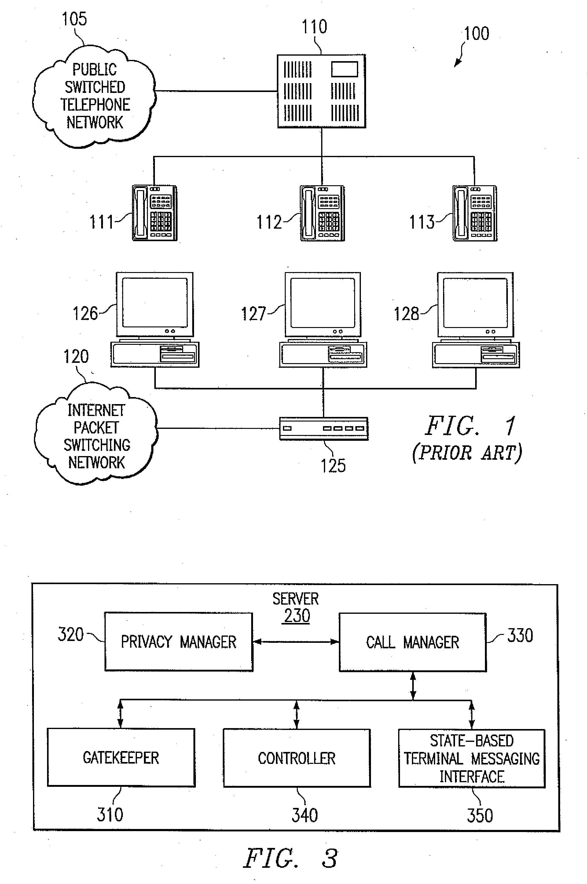
[0032]Referring initially to FIG. 1, illustrated is a schematic diagram showing a prior art system100 with totally separate voice and data communication networks. The system 100 includes an external public switched telephone network 105, an internal PBX 110, and telephone end terminals 111, 112, 113 on the voice side. The system 100 includes an external internet packet switching network 120, an internal gateway 125, and end terminal desktop computer systems 126, 127, 128 on the data side. This environment requires completely separate voice network and data network wiring systems often serviced and maintained by two separate departments. The PBX 110 is an internal, private telephone routing and switching device which connects incoming voice messages to the appropriate internal telephone extension and outgoing voice messages to the appropriate external telephone by working in concert with the external, public switched telephone network 105. The gateway 125 is an internal translating d...


PUM


Abstract

A system for, and method for, performing state-based signaling on behalf of a stateless client. In one embodiment, the system includes a controller, couplable to a state-based terminal, that translates at least one stateless signaling message received from the stateless client to at least one state-based signaling message for presentation to the state-based terminal thereby facilitating a media stream communications session between the stateless client and the state-based terminal over an Internet Protocol (IP)-based network.

Description

CROSS-REFERENCE TO RELATED APPLICATION[0001]This application is a continuation of U.S. application Ser. No. 09 / 032,083 filed Feb. 27, 1998 and entitled “System and Method for Performing Signaling on Behalf of a Stateless Client.”TECHNICAL FIELD OF THE INVENTION[0002]The present invention is directed, in general, to communication systems and, more specifically, to a system and method for performing signaling on behalf of a stateless client and a communications network employing the same.BACKGROUND OF THE INVENTION[0003]Under the definitions of the International Telecommunications Union-Telecommunications Sector (ITU-T) Recommendation H.323 and related documents, it is assumed that the compliant communications endpoints contain all of the intelligence necessary to perform the protocols and procedures specified within these documents. Due to the complexity of these specifications, a significant computational power requirement is placed upon these endpoints. These current standards-base...

Claims


Application Information

Patent Timeline
Patent Type & Authority Applications(United States)
IPC IPC(8): G06F15/16
CPCH04L65/104H04L65/1053H04L65/103H04L65/1059H04L65/1069
Inventor BELL, ROBERT T.HAHN, PAUL S.MCCLUNG, MICHAEL H.PLATT, RICHARD B.
Owner CISCO TECH INC
Learn More