Electric Fireplace with Flame Curtain

a technology of electric fireplace and flame curtain, which is applied in the field of electric fireplaces, can solve the problems of complex structure and installation, and achieve the effects of dull appearance, increased realism of charcoal flames, and enhanced bottom structure and three-dimensional characteristics

Inactive Publication Date: 2010-08-19
ZHU HONGFENG
View PDF4 Cites 1 Cited by
  • Summary
  • Abstract
  • Description
  • Claims
  • Application Information

AI Technical Summary

Benefits of technology

[0013]As a metamorphic exemplary embodiment of the flame curtain with vessel structure, the bottom of the front wall of the vessel is protrusive to form a concave groove inside, the concave groove has a trapezoid cross-section. By fulfilling the concave groove of the vessel with charcoals, the bottom structure of the charcoal flame is improved to be more three-dimensional, so is the felling of the charcoal flame. The concave groove with trapezoid cross-section makes the transition of upper and lower charcoal flame more nature and close to the nature configuration of real charcoal flame.
[0014]As a metamorphic exemplary embodiment of the flame curtain with transparent plate structure, a lower end of the transparent plate bends forward to be L-shaped portion, the charcoal bed has a L-shaped portion corresponding to the L-shaped portion of the transparent plate and is attached thereon. A charcoal bed with inclined structure is formed on the electric fireplace, which enhances the bottom structure and the three-dimensional characteristic of the charcoal flame structure, and gets close to its nature configuration. The bending structure could be disposed at the lower end of both the flat and the curved surface structure of the transparent plate.
[0015]Preferably, a bottom flame generator is disposed at the bottom portion of the vessel, the bottom flame generator includes a rotating axis driven by electric machinery and reflecting strips disposed on the rotating axi

Problems solved by technology

In addition, the image screen and the charcoal bed of a traditional fireplace are disposed separately; the installation structure

Method used


Image

  • Electric Fireplace with Flame Curtain
  • Electric Fireplace with Flame Curtain
  • Electric Fireplace with Flame Curtain

Examples


embodiment 1

Preferred Embodiment 1

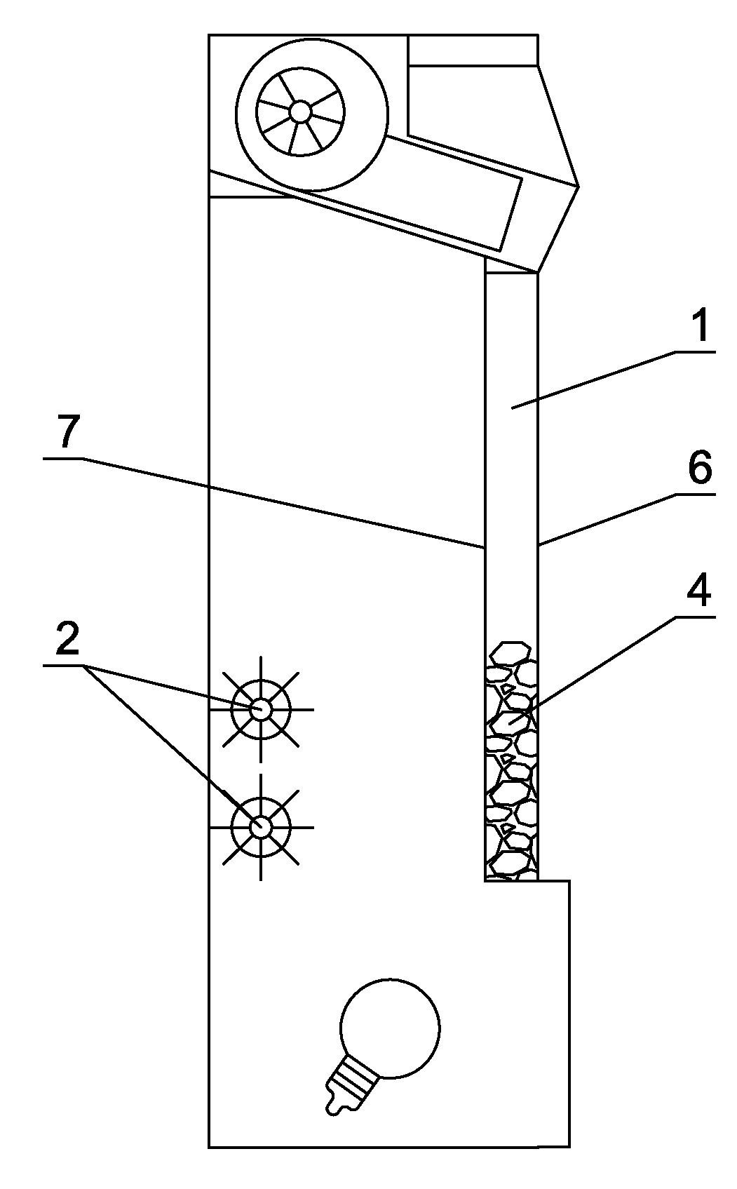
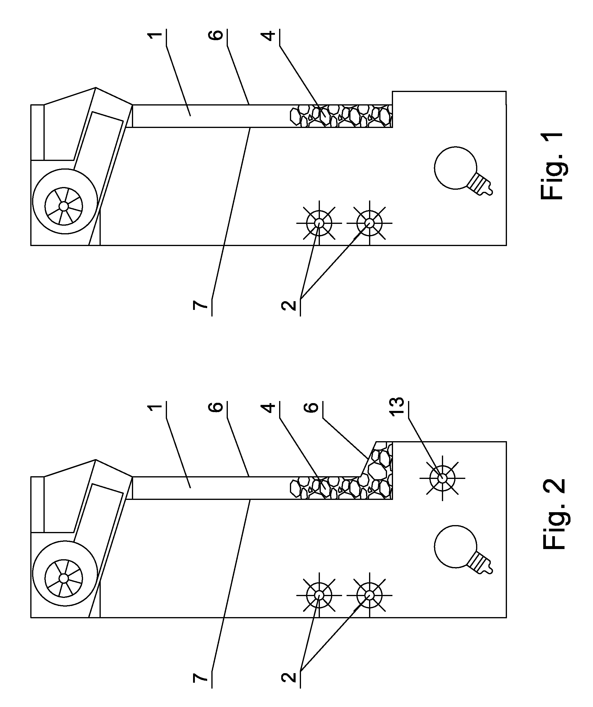
[0028]As shown in FIG. 1, an electric fireplace with a flame curtain comprises a housing, a light source, a flame curtain 1 with integral structure being disposed on the electric fireplace (as shown in FIG. 5 and FIG. 9) and in front of an electric fireplace flame generator 2, the flame generator includes a rotating axis driven by electric machinery and reflecting strips disposed on the rotating axis, the flame curtain 1 is a kind of structure of vessel, a front wall 6he a rear wall 7 of the vessel are transparent and the size of the rear wear 7 are the same as the front wall 6, the imaging mechanism 3 is disposed on the front wall 6 of vessel, and the imaging mechanism 3 is a mat surface structure disposed on the front wall 6 of the vessel, the size of the mat surface structure matches the size of the front wall 6 of the vessel.

[0029]A number of moveable light-holding charcoals 5 with a plurality of transparent surfaces and a plurality of simulative charcoals ...

embodiment 2

Preferred Embodiment 2

[0030]As shown in FIG. 2, the bottom of the front wall 6 of the vessel is protrusive to form a concave groove 12 inside, the concave groove 12 has a trapezoid cross-section (as shown in FIG. 6). A number of moveable light-holding charcoals 5 with a plurality of transparent surfaces and a plurality of simulative charcoals 11 with natural charcoal shape are disposed in the vessel. A proportion of the simulative charcoals 11 and the light-holding charcoals 5 is 1:4. The imaging mechanism 3 is a thin image screen attached to the front wall 6 of the vessel, the size of the thin image screen matches the size of the front wall 6 of the vessel. A bottom flame generator 13 is disposed at the bottom portion of the vessel. The bottom flame generator 13 includes a rotating axis driven by electric machinery and reflecting strips disposed on the rotating axis. The other structures are the same as that in the first preferred embodiment.

embodiment 3

Preferred Embodiment 3

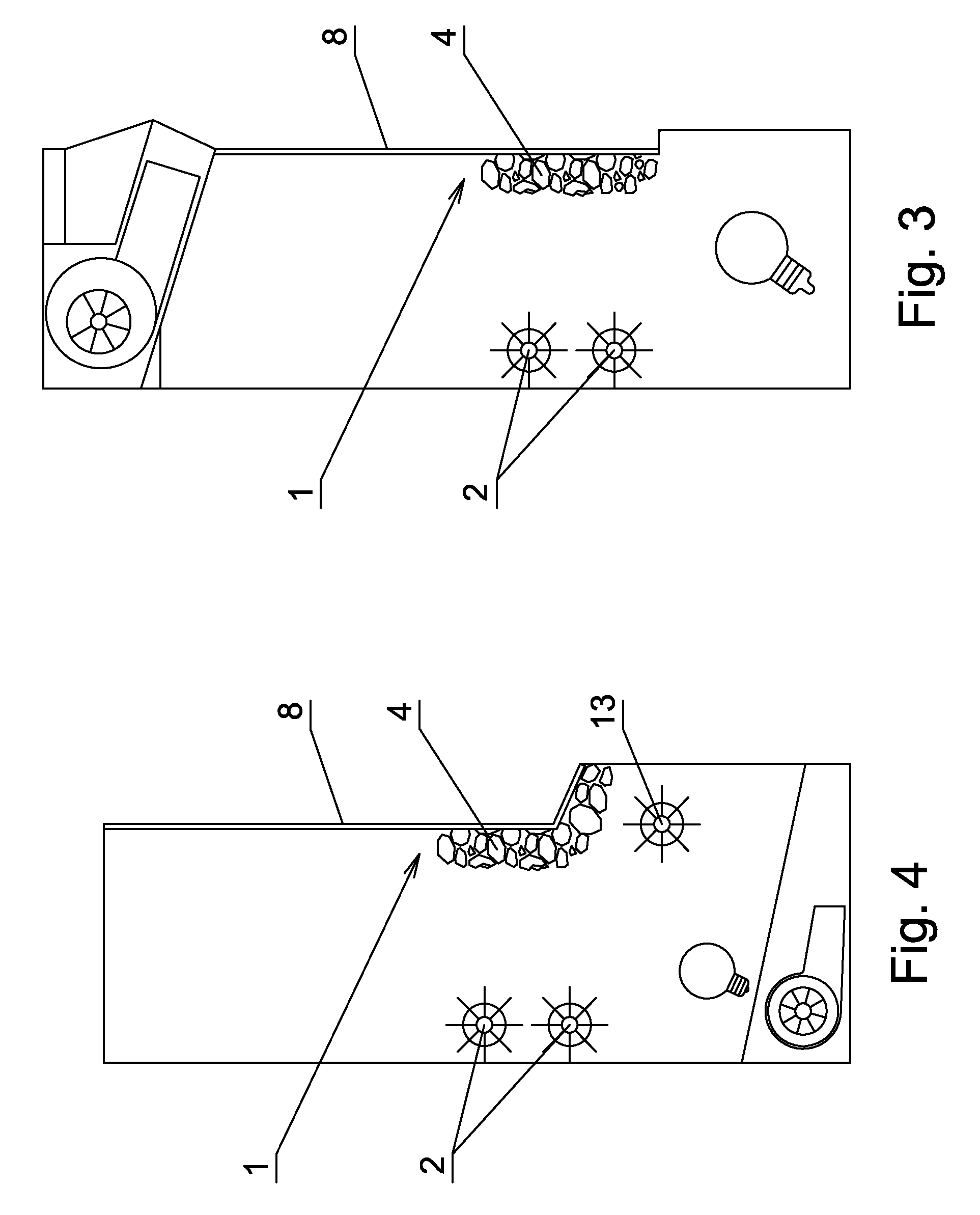
[0031]As shown in FIG. 3, an electric fireplace with a flame curtain comprises a housing, a light source, a flame curtain 1 with integral structure being disposed on the electric fireplace (as shown in FIG. 7 and FIG. 10), the flame curtain 1 includes a transparent plate 8 and a charcoal bed 4 disposed on the transparent plate 8. The flame curtain 1 is disposed in the front of an electric fireplace flame generator 2, the flame generator 2 includes a rotating axis driven by electric machinery and reflecting strips disposed on the rotating axis. The transparent plate is a grass flat plate with a mat structure disposed on the side near to flame generator, the size of the mat structure matches the size of the transparent plate. The charcoal bed 4 is disposed on the mat structure. The charcoal bed 4 includes a number of light-holding charcoals 5 with a plurality of transparent surfaces and a plurality of simulative charcoals 11 with natural charcoal shape. A proport...


PUM


Abstract

The invention relates to a An electric fireplace with a flame curtain comprises a housing, a light source, a flame curtain with integral structure being disposed on the electric fireplace and in front of an electric fireplace flame generator, an imaging mechanism and a charcoal bed being disposed on the flame curtain, and a number of light-holding charcoal with a plurality of transparent surfaces being disposed on the charcoal bed. The essential effect of the present invention is to solve the problems of constant charcoal flame brightness, the lacking of reality and the bad charcoal flame simulation effect in conventional electric fireplaces. Meanwhile, the problems of constant charcoal flame shape, dull appearance and poor visual effect in conventional electric fireplace are solved as well. The present invention is of simple structure and easy assembly process, while the charcoal flame structure can be arbitrarily changed, the light-spots of the flame are sparkling intermittently with bright and shade, and the flame is of light-holding effect. The visual effect and the authenticity are both perfect.

Description

FIELD OF THE INVENTION[0001]The present invention relates to an electric fireplace, more particularly, an electric fireplace with a flame curtain.BACKGROUND OF THE INVENTION[0002]Conventional fireplace simulator structures are divided into two types by the simulation of the burning substance of the fireplace. One is a simulation of burning flame by projecting varying light onto an image screen with imaging operation. Such as the flame simulator of electric fireplace disclosed in the patent with publication date Sep. 5, 2007 and publication number CN 200944291, comprises a light source, a flame board, a translucent image screen, a light shade with a transparent hole, a simulative fuel bed in front of a housing chamber. The light shade with a transparent hole is disposed at the back of the flame board, and a glass screen is fixed in front of the image screen. The light source cooperates with the light shade, and the light shade cooperates with a transmission mechanism. In the structur...

Claims


Application Information

Patent Timeline
IPC IPC(8): G09F19/12
CPCF24C7/004
Inventor ZHU, HONGFENG
Owner ZHU HONGFENG
Why Eureka
Try Eureka