Assembly, system and method for automated vertical moment connection

a technology of vertical moment connection and assembly system, which is applied in the field of welding, can solve the problems of long and laborious process of either option, and achieve the effects of facilitating the speed of erecting a low-rise, facilitating the welding of vertical moment connection, and reducing labor intensity

Inactive Publication Date: 2010-08-19
ESKANDARI AMIR
View PDF8 Cites 38 Cited by
  • Summary
  • Abstract
  • Description
  • Claims
  • Application Information

AI Technical Summary

Benefits of technology

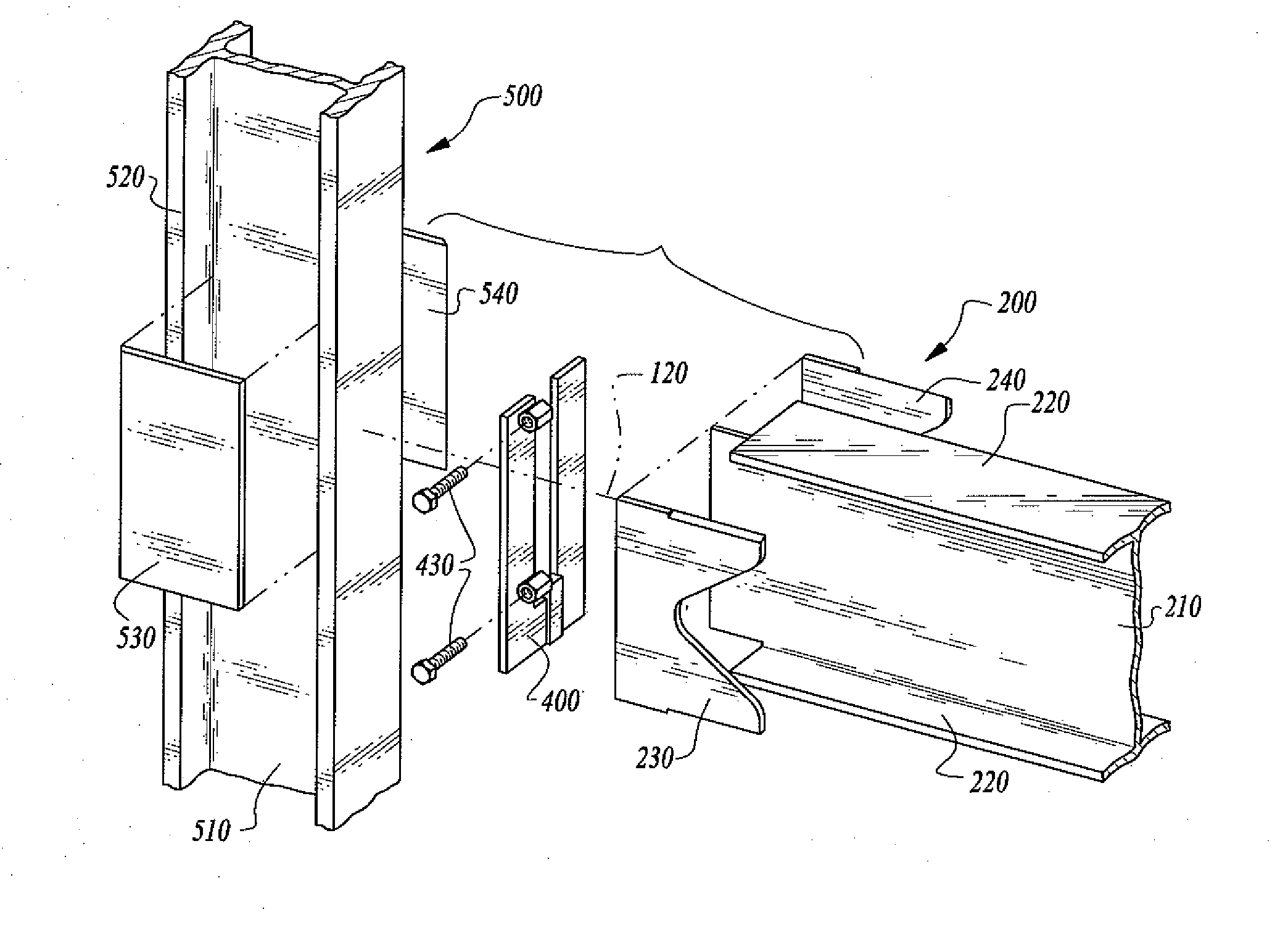
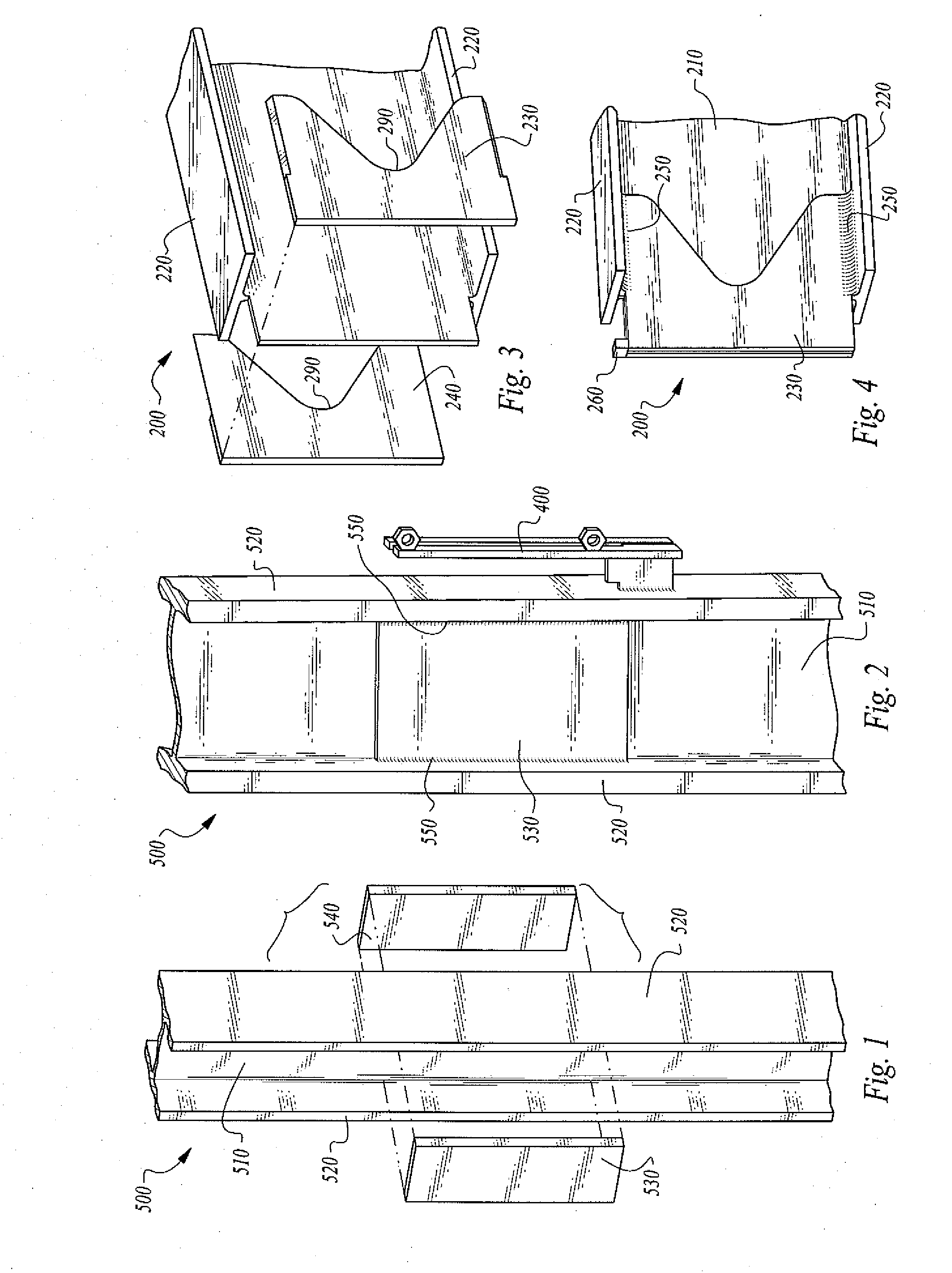
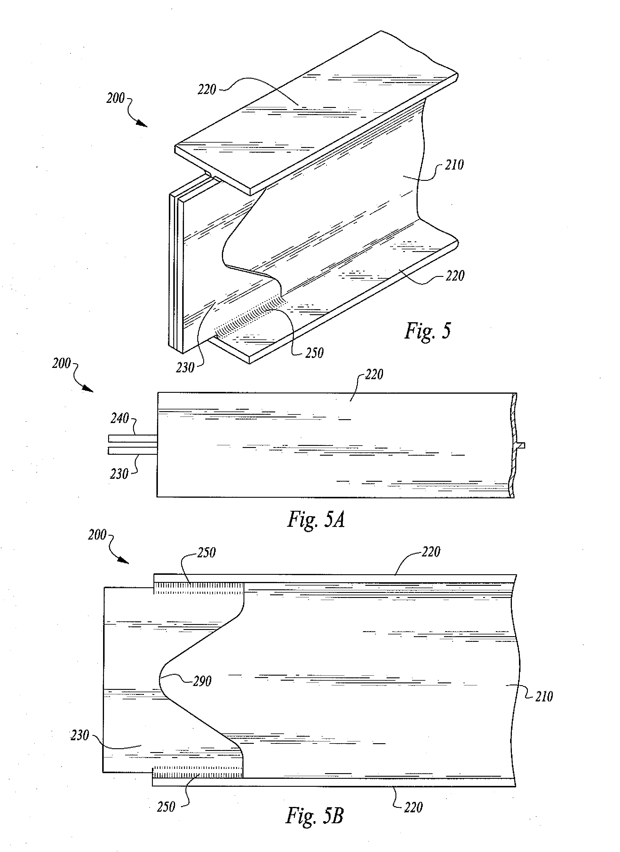
[0014]When erecting high-rise buildings (on site), horizontal beam flanges are welded to vertical column flanges by either (1) multipass “gasless flux-core” wire welding process, or (2) multipass “gas shielded flux-core” wire welding process. Either option presents a long and laborious process. To facilitate the speed of erecting a low-rise or high-rise building, Arcmatic™ has devised an assembly, system and method of automating the welding process to make the moment connection much stronger by welding doubler plates to the vertical column web and the horizontal beam web at the beam-to-column moment connection. This assembly, system and method also makes vertical moment connection welds much faster by using a newly designed mechanized and automated welding system to facilitate the welding process, to reduce welding time, and to strengthen the weld beam-to-column flange weld connection while erecting the building “on the job.” Further, this beam-to-column moment connection assembly, method and system is applicable to any current welding techniques, processes, or systems including, but not limited to, solid state computer controlled welding, flux-cored wire welding, metal-core wirer welding, gas meal arc welding, resistance welding, arc welding, electron beam welding, Electroslag welding, induction welding, laser beam welding, thermit welding, or any other welding process.
[0030]c) placing copper runoff blocks 260 on top of the web plate horizontal beam web 210 and doubler plates, 230 and 240, and the vertical column flange plates to keep the weld puddle from running down the submerged arc weld joint when the VertaSlag™ weld reaches the top of the weld cavity 440;

Problems solved by technology

Either option presents a long and laborious process.

Method used


Image

  • Assembly, system and method for automated vertical moment connection
  • Assembly, system and method for automated vertical moment connection
  • Assembly, system and method for automated vertical moment connection

Examples


example case

[0121 through section 1-1

Partialforce=(Bbf(-)Tc)2(X)Btf(X)Fb(X)SF10

Shear through Section 1-1=Lw1(X)Btf(X)Fv  11

[0122]Equate: #10 and #11

(Bbf(-)Tc)2(X)Btf(X).66Fy(X)SF=Lw1Btf(X).4Fy∴Lw1=SF.66[Bbf(-)Tc].4(X)2=.825(X)SF[Bbf(-)Tc]12

[0123]Where Lw1=minimum length at weld required at path 1-1

[0124]Case through section 2-2:

Total Force=SF(X)Bbf(X)Btf(X)Fb  13

Shear through 2-2=Lw2(X)Tc(X)Fv  14

[0125]Equating formulas #13 and #14

SF(X)Bbf(X)Btf(X)0.66(X)Fy=Lw2(X)Tc(X)0.4(X)Fy

∴Lw2=SF(X).66.4Bbf(X)BtfTc∴Lw2=1.65(X)SF(X)Bbf(X)BtfTc15

[0126]Where Lw2=minimum length of weld required through path 2-2[0127]Select as Lw the Larger value of Lw1 or Lw2

[0128]6. Slope of Beam Doubler Plate[0129]Calculate the optimal “slope” on the beam doubler plate “b” to insure even shear stress distribution on the weld through its length “Lw” (FIGS. 13, 15 and 16)[0130]The maximum shear force transferred from the beam flange to Plate “b” is:

Shear=Lw(X)Tb(X)Fv  16

Maximum pull on plate “b” at 3-3=Tb(X)Lb(X)Fb  17

[0131]Equ...


PUM

PropertyMeasurementUnit
forceaaaaaaaaaa
thicknessaaaaaaaaaa
shear stressaaaaaaaaaa

Abstract

An automated assembly, system and method for a narrow-gap Electroslag-welded moment connection welded between horizontal beam to vertical column flanges includes vertical column doubler plates affixed to the column web and horizontal beam doubler plates affixed to the beam web with alignment of the respective webs / doubler plates to carry the moment load through the vertical support columns. An embodiment includes a radius in each horizontal beam doubler plate. The assembly, system and method is readily applicable to overdesign moment load factors.

Description

CROSS-REFERENCES TO RELATED APPLICATIONS[0001]This application is based upon and claims the priority of U.S. Provisional Patent Application Ser. No. 61 / 152,818, filed Feb. 16, 2009.STATEMENT REGARDING FEDERALLY SPONSORED RESEARCH OR DEVELOPMENT[0002]None.REFERENCE TO A MICRO-FICHE APPENDIX[0003]None.TECHNICAL FIELD[0004]This invention relates to welding. More particularly, the invention is related to an assembly, system and method for automated narrow-gap Electroslag-welded moment connections (welded between the two vertical column flanges) for the construction of low-rise and high-rise buildings.BACKGROUND OF THE INVENTION[0005]My U.S. Pat. No. 6,297,472 [the “'472 patent”], issued Oct. 2, 2001, discloses and claims a welding system and method including a distributed welding control system that allows a welding operator to program automated welding cycles for various welding operations, and that is particularly useful for installing stiffener plates onto structural beams. In U.S. P...

Claims


Application Information

Patent Timeline
Patent Type & Authority Applications(United States)
IPC IPC(8): E04B1/58B23K25/00E04C3/02
CPCE04B2001/2448Y10T29/49634Y10T29/49625B23K33/004Y10T29/49623E04B2001/2415E04B2001/2445B23K2201/28E04B1/2403Y10T29/49631B23K2101/28
Inventor BONG, WILLIAM L.
Owner ESKANDARI AMIR
Why Eureka
Try Eureka