
Endless stream fish tank

Inactive Publication Date: 2010-08-19
KEEPALIVE
View PDF17 Cites 16 Cited by
  • Summary
  • Abstract
  • Description
  • Claims
  • Application Information

AI Technical Summary

Benefits of technology

[0004]The object of the invention is therefore to overcome the above-mentioned drawbacks of the prior art live-fish tanks and to provide a fish tank, either portable or installed in a boat as a livewell, that (a) will provide an environment to allow small or large fish to swim in a more natural state, and (b) is smaller and lighter than the conventional bait and fish tanks, and thus save deck space and reduce the weight added to the boat.
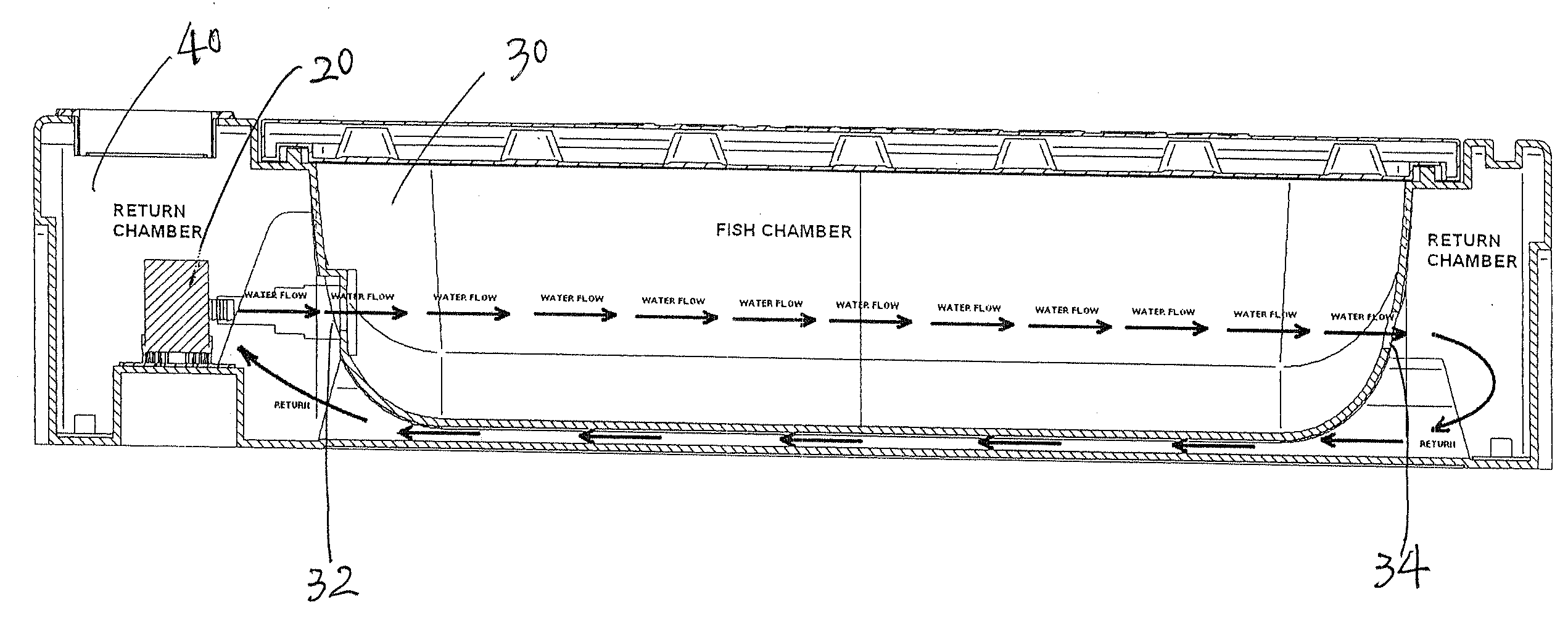
[0005]The above object is achieved by producing continuous water movement in one direction in a long and narrow swim space defined within a tank. In one embodiment the tank includes an inner container for fish to swim in and an outer container for facilitating water circulation. The water enters the inner container at one end through an entry hole and exits the inner container into the outer container at the other end of the inner container through an exit hole, and then returns to the entry hole back into the inner container. This creates an endless stream in the inner container. During the circulation of the water, it can also provide aeration required for fish within the inner container. This tank simulates a more natural movement of water for fish survival. The fish will swim upstream and in one direction. Water speeds may be adjusted according to the swimming speeds of the species of fish contained in the inner container by a pump installed in the outer container to provide a self contained unit. The pump is preferably designed to also function as an aeration unit, introducing atmospheric air, or oxygen from an oxygen bottle, directly into the water as it is being circulated.
[0006]The endless stream fish tank or livewell according to the invention has the advantage that it requires less space than the conventional large volume, round, oval or square tanks or livewells. It is long and narrow and can be placed inside or alongside the gunwales of a boat allowing more passenger space.

Problems solved by technology

The size of the fish that can be maintained is limited by the diameter of the tank.
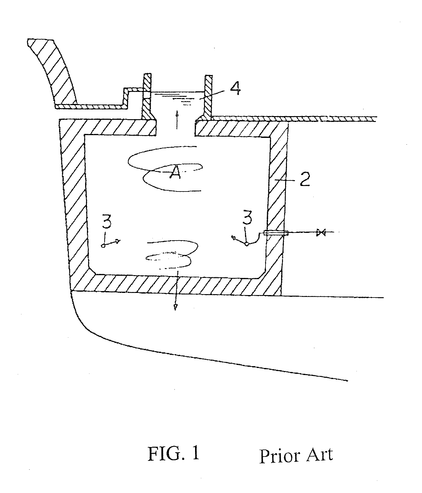
These types of tanks are not only stressful for the fish, but cumbersome, and take up valuable deck space for passengers, increase the weight of the boat, and may also cause safety hazards.
The fish tank disclosed by JP 59-167396 A must be large in order to maintain live fish, which is disadvantageous particularly onboard a boat where space and weight are limited.

Method used


Image

  • Endless stream fish tank
  • Endless stream fish tank
  • Endless stream fish tank

Examples


Embodiment Construction

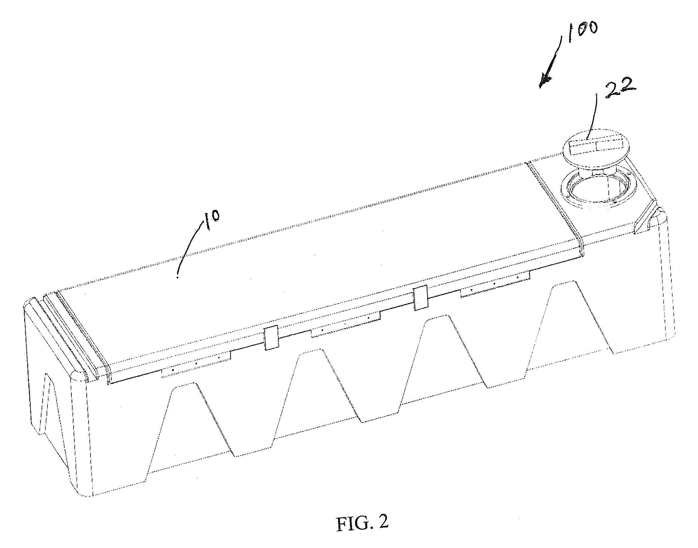
[0028]FIGS. 2-5 show an embodiment of a single tank configuration of the present invention. FIG. 2 is a perspective view of the single tank configuration. As can be seen in FIG. 2, the single tank 100 has an elongated narrow and square shape and has a tank lid 10 which can be opened up when putting fish in the tank or getting fish out of the tank. The tank lid 10 is closed during normal operating conditions. The tank lid 10 can be connected to one side of the outer container 40 by hinges or any other connecting mechanism. A pump lid 22 for a pump 20 (see FIG. 4) installed inside the tank is shown at one end of the tank. The pump lid 22 can be lifted when adding water into the tank or servicing the pump 20.

[0029]FIG. 3 is a horizontal cross-sectional view of the single tank configuration as shown in FIG. 2. As can be seen in FIG. 3, the tank 100 includes an inner container 30 and an outer container 40, which have similar shapes. The inner container functions as a fish chamber. The sp...


PUM


Abstract

An endless flow fish tank, which occupies relatively little space, yet allows instinctively swimming fish to swim comfortably. Aerated water is pumped in one direction through a swim chamber, and water returns through a space between inner and outer container, through return flow piping, or through a second swim chamber which also serves as a return flow chamber.

Description

FIELD OF THE INVENTION[0001]The present invention relates in general to a fish tank, either portable or installed in a boat as a livewell, for keeping fish or bait alive in a healthy condition and, more specifically, to a portable fish tank or a livewell that provides an artificial current in the water for species of fish that require continuous movement to keep them in a healthier and less stressed environment.BACKGROUND OF THE INVENTION[0002]In order to maintain species of fish that require continuous movement through the water, an artificial current must be provided in portable tanks or livewells to ensure their survival. Fast swimming fish will school in the current along the perimeter of the tank. The size of the fish that can be maintained is limited by the diameter of the tank. Larger fish would need an extremely large tank to ensure that they can swim without their bodies being continuously curved and causing them damage. These types of tanks are not only stressful for the f...

Claims


Application Information

Patent Timeline
IPC IPC(8): A01K63/04A01K63/00A01K63/02
CPCA01K63/02A01K63/042A01K61/00A01K61/10
Inventor VENTO, THOMAS JOSEPH
Owner KEEPALIVE
Learn More