Dispenser of fluid products

Active Publication Date: 2010-08-19
APTAR ITAL
View PDF9 Cites 16 Cited by
  • Summary
  • Abstract
  • Description
  • Claims
  • Application Information

AI Technical Summary

Benefits of technology

[0024]Another object of the present invention is to propose a dispenser

Problems solved by technology

Disadvantageously, this type of dispenser is frequently subjected to blocks determined by the sliding of the piston inside the dosing chamber.
This makes the productive process more complex and expensive.
Also, the presence of metallic components, e.g. the return valve and/or the ball, sets substantial limits both in terms of usage capability, since possible contact with the product can determine corrosion problems, and of the possibility to recyc

Method used


Image

  • Dispenser of fluid products
  • Dispenser of fluid products
  • Dispenser of fluid products

Examples


Example

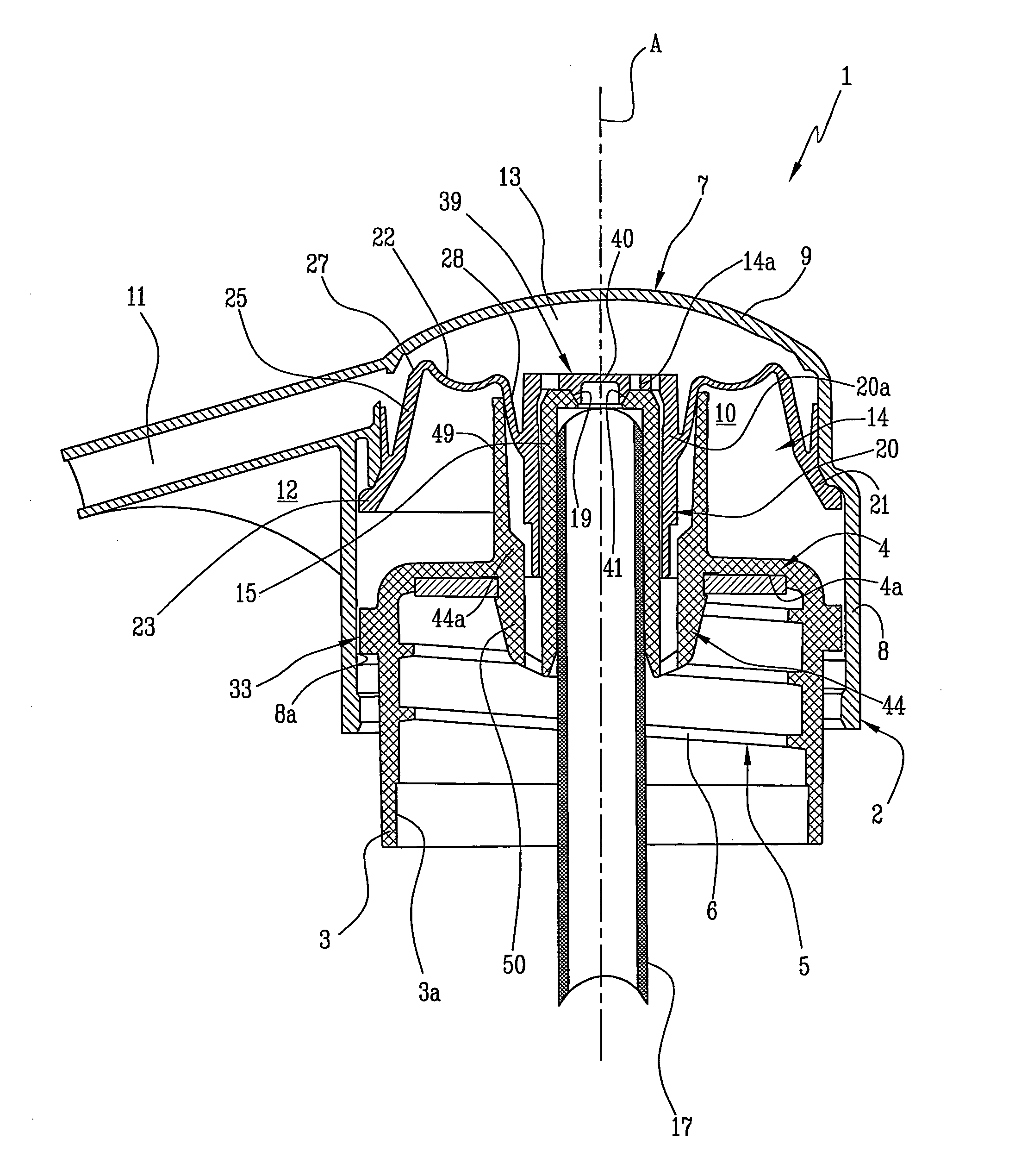
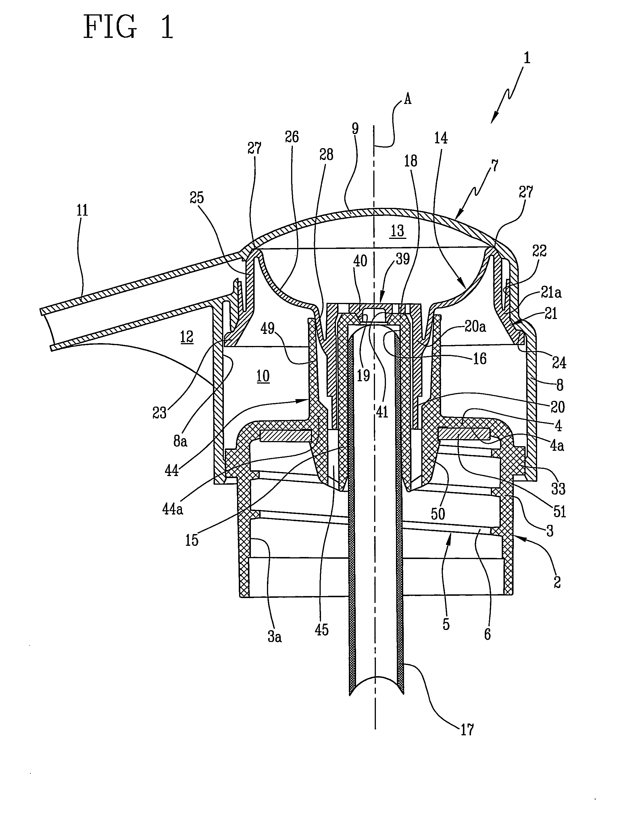
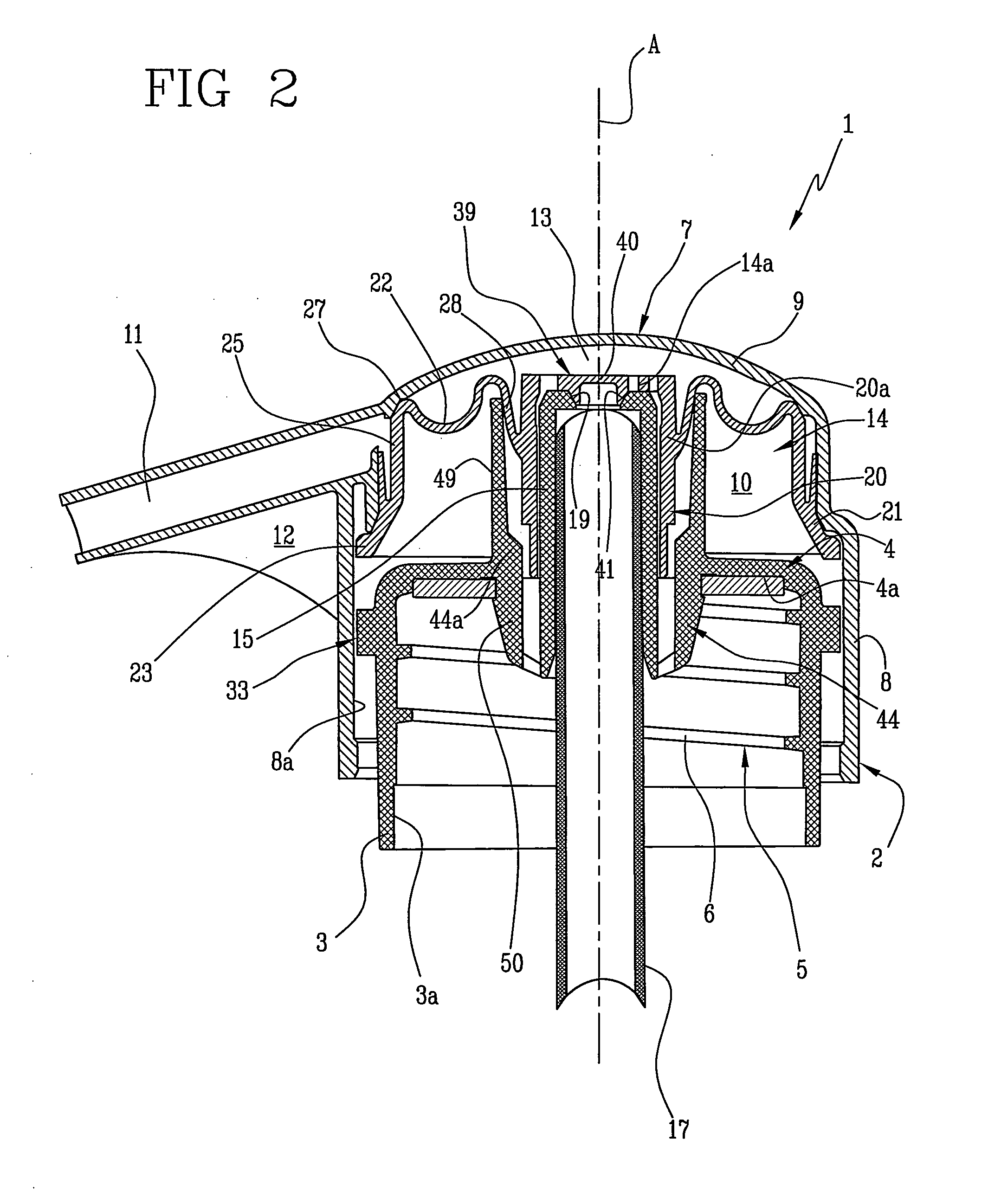
[0038]With reference to the accompanying figures, the reference number 1 indicates in its entirety a dispenser of fluid products according to the present invention.

[0039]The dispenser 1 comprises a ring nut 2 able to be associated to a container of a fluid product (not shown) comprising a lateral cylindrical wall 3 and an annular wall 4 to obstruct an access to the container.

[0040]The ring nut 2 comprises coupling means 5 to fasten the ring nut 2 to the container. In the described embodiment, the coupling means 5 comprise a helical thread 6 obtained on an inner surface 3a of the cylindrical wall 3 of the ring nut 2. Said thread 6 can be coupled to a corresponding thread of the container, not shown.

[0041]In an alternative embodiment, not shown, the association means 5 comprise a circular undercut that engages in a groove obtained on the container.

[0042]The dispenser 1 further comprises a substantially hollow dispensing head 7, coaxially slidable relative to the ring nut 2 and made of...


PUM


Abstract

A Dispenser of fluid product includes a ring nut (2) able to be associated with a container of a fluid product and a dispensing head (7), substantially hollow and coaxially slidable relative to the ring nut. The dispensing head includes a dosing chamber (13) positioned inside the dispensing head, a dispensing nozzle (11) to allow escape of the fluid product. The dispensing head further includes a deformable membrane (14) fastened to the ring nut and a top wall (9) facing the membrane and defining the dosing chamber in combination with the membrane; the top wall being movable between a first position, distal from the ring nut, in which a volume of the dosing chamber is greatest and the dosing chamber is isolated and at least in part filled with fluid product, and a second position, proximal to the ring nut, in which the volume of the dosing chamber is smallest.

Description

TECHNICAL FIELD[0001]The present invention relates to a dispenser of fluid products. In particular, the present invention relates to a device for metering and dispense viscous fluid products, such as liquid soaps, lotions or the like contained in appropriate containers.BACKGROUND ART[0002]Dispensers of fluid products are known which are screwed on a container in a fluid product to be dispensed and which, therefore, also serve as closing stoppers for said containers.[0003]Known dispensers comprise a dosing chamber with variable volume to aspirate and subsequently dispense a portion of the fluid product from the container.[0004]In detail, when the volume of the dosing chamber is reduced, the overpressure thus determined expels the portion of fluid product contained towards the exterior, whilst when the volume of the dosing chamber is increased the vacuum thus created aspirates a successive portion of product from the container to the dosing chamber. Appropriate check valves regulate t...

Claims


Application Information

Patent Timeline
IPC IPC(8): B65D37/00
CPCB05B11/0016B05B11/3059B05B11/3033B05B11/3028B05B11/0044B05B11/1028B05B11/1033B05B11/1059
Inventor CARTA, LAMBERTO
Owner APTAR ITAL
Why Eureka
Try Eureka