

Thermal imaging camera
a thermal imaging and camera technology, applied in the field of portable thermal imaging cameras, can solve the problem of often greatly limited visibility
- Summary
- Abstract
- Description
- Claims
- Application Information
AI Technical Summary
Benefits of technology
Problems solved by technology
Method used
Image

Examples
Embodiment Construction
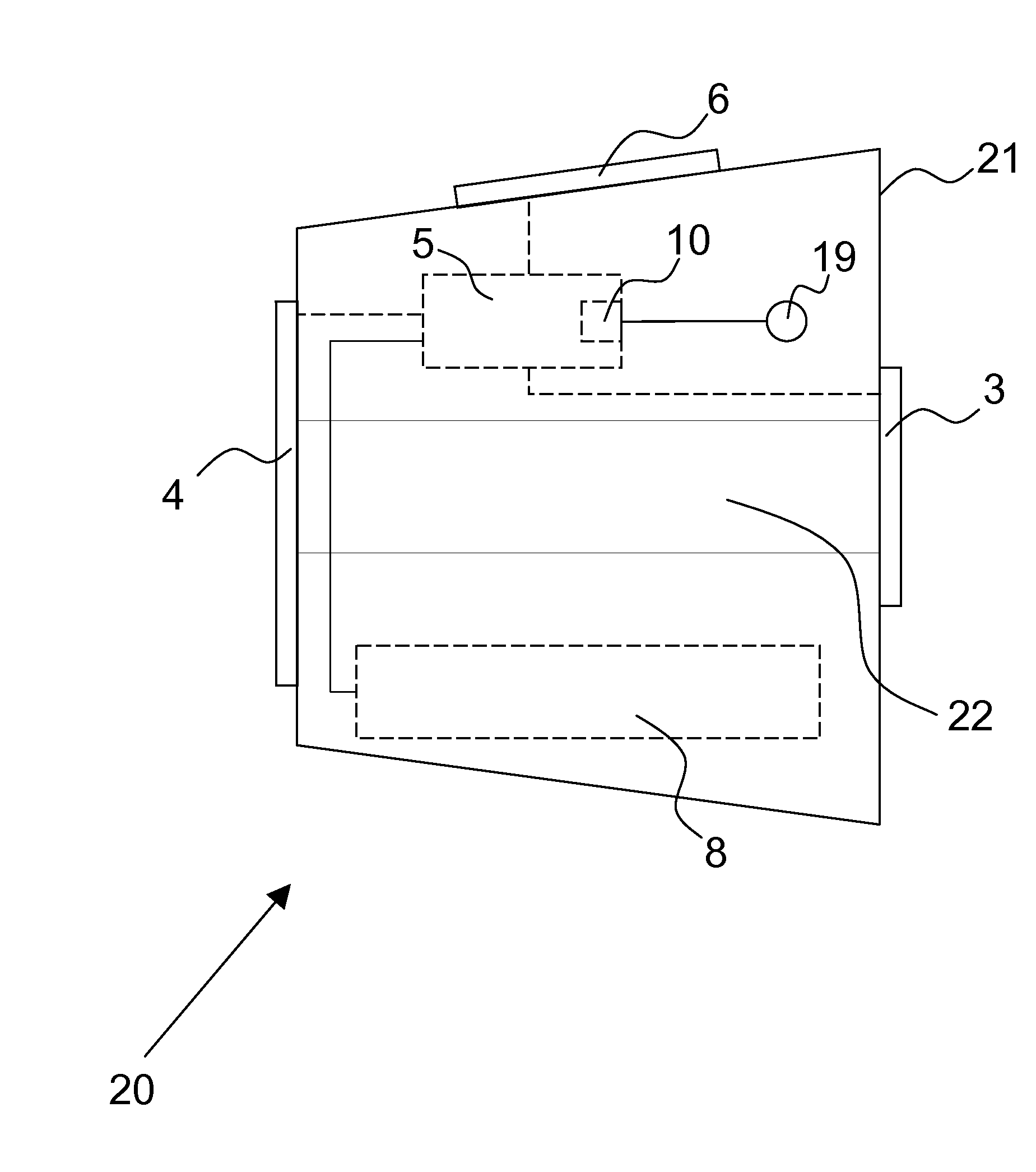
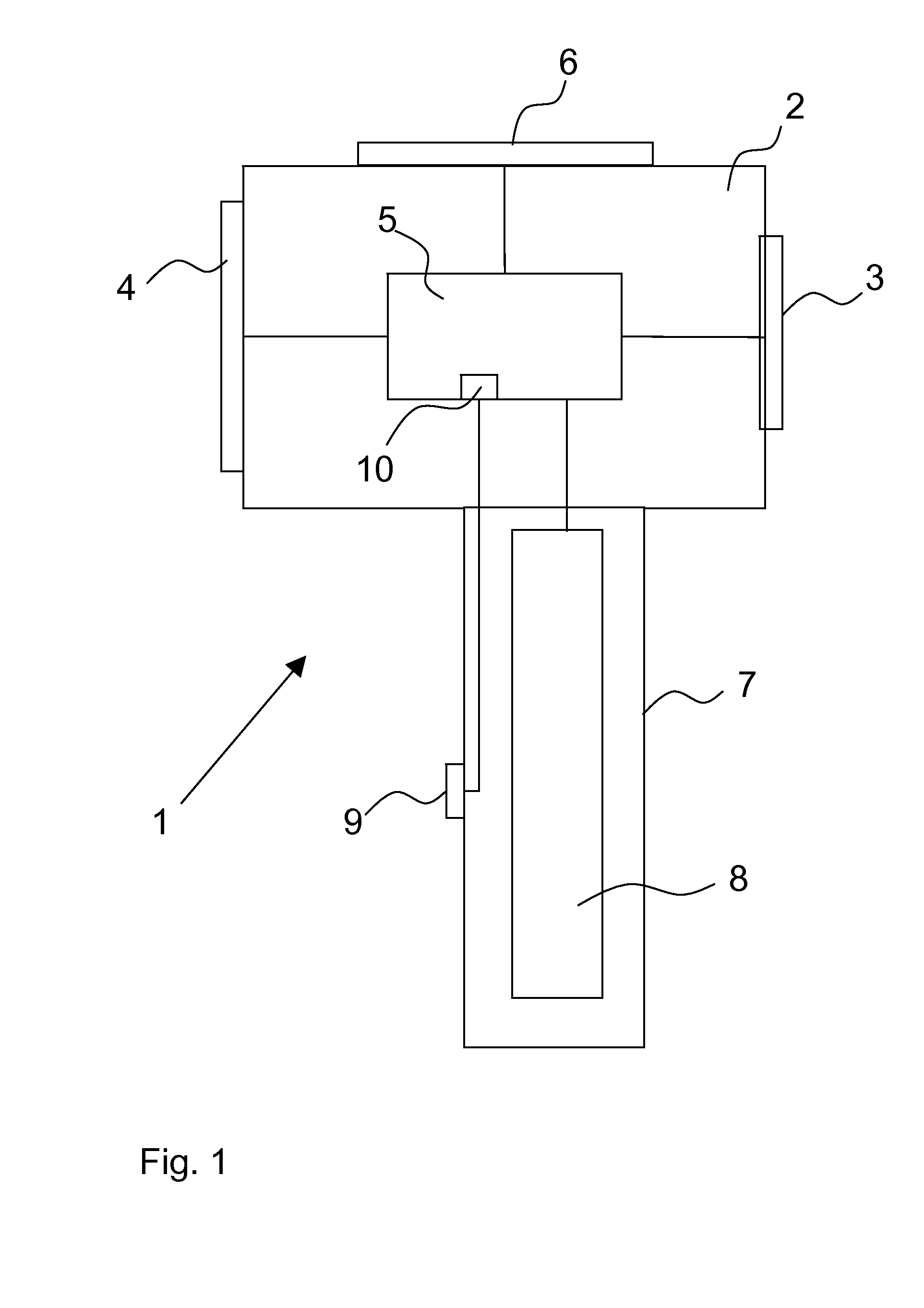
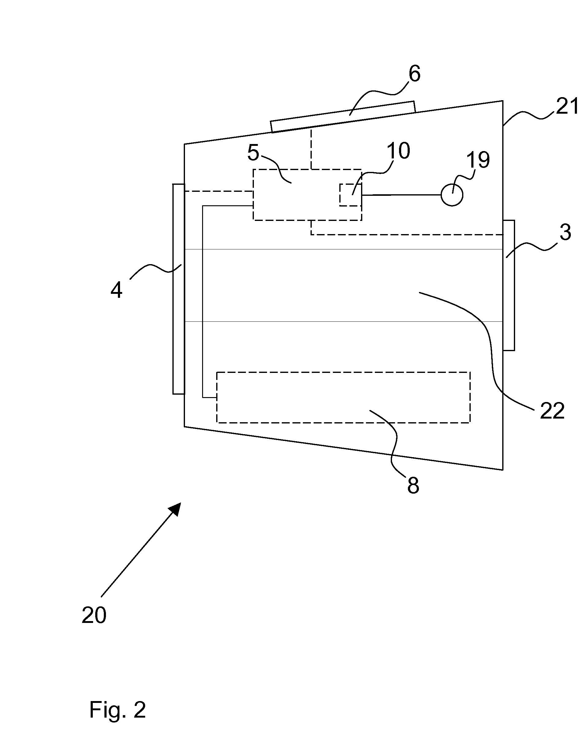
[0018]Referring to the drawings in particular, FIG. 1 schematically shows a first thermal imaging camera 1, in which an optical image detection means 3, a display means 4 for outputting thermal image data and a control unit 5 for processing the thermal image data detected are accommodated in a camera housing 2. An operating unit 6, via which the different functions of the device can be activated, is located on the top side of the camera housing 2. A handle 7, which contains a battery pack 8 as the energy supply of the thermal imaging camera 1, is attached to the underside of the camera housing 2 as a carrying device. A capacitive sensor 9, which is connected to the control unit 5 and generates a switching signal when the handle 7 is grasped by a hand of a user, which hand is not shown in FIG. 1, is arranged as a sensor element on the outside of the handle 7. A switching signal is likewise generated in the reversed case, when the user lets go of the handle 7. A switch from the standb...
PUM
 Abstract
Description
Claims
Application Information