Motor controller and motor control method

a technology of motor controller and control method, which is applied in the direction of mechanical control devices, dynamo-electric gear control, dynamo-electric converter control, etc., can solve the problems of reducing phase margin, delay in the execution of the motor control operation, and deteriorating precision to a certain degree, and achieve high precision

Active Publication Date: 2015-04-28
RICOH KK
View PDF11 Cites 1 Cited by
  • Summary
  • Abstract
  • Description
  • Claims
  • Application Information

AI Technical Summary

Benefits of technology

[0012]At least one embodiment of the present invention provides a motor controller and a motor control method that substantially obviate one or more problems caused by the limitations and disadvantages of the related art. Specifically, a motor controller controls the position and the velocity of a motor by regularly processing interrupts with high precision and without causing a delay of the processing or collapse of control, even if the processing includes a number of operations to be executed with an inexpensive CPU or a microcomputer.
[0014]According to at least one embodiment of the present invention, it is possible to provide a motor controller that controls the position and the velocity of a motor by regularly processing interrupts with high precision and without causing a delay of the processing or collapse of control, even if the processing includes a number of operations to be executed with an inexpensive CPU or a microcomputer.

Problems solved by technology

Patent document 1 above deals with a problem in that precision of control deteriorates when another interrupt routine has priority over the interrupt routine for motor controlling, resulting in a delayed execution of a motor controlling operation.
However, even using the technology in Patent document 1, it is inevitable that precision deteriorates to a certain degree.
Moreover, a delay between the sampling and the output of the motor drive quantity causes a phase delay of the control quantity, which reduces phase margin and destabilizes control according to the feedback control theory.
In the worst case, oscillation or other unstable states may be induced.
However, both conventional technologies may have a possibility that an interrupt process does not end within a prescribed cycle, if the number of operations to be executed during the interrupt process increases.
If that is the case, normal operations cannot be completed, resulting in a state of collapse.
Simply shortening the cycle or using a software counter may be problematic.

Method used


Image

  • Motor controller and motor control method
  • Motor controller and motor control method
  • Motor controller and motor control method

Examples


first embodiment

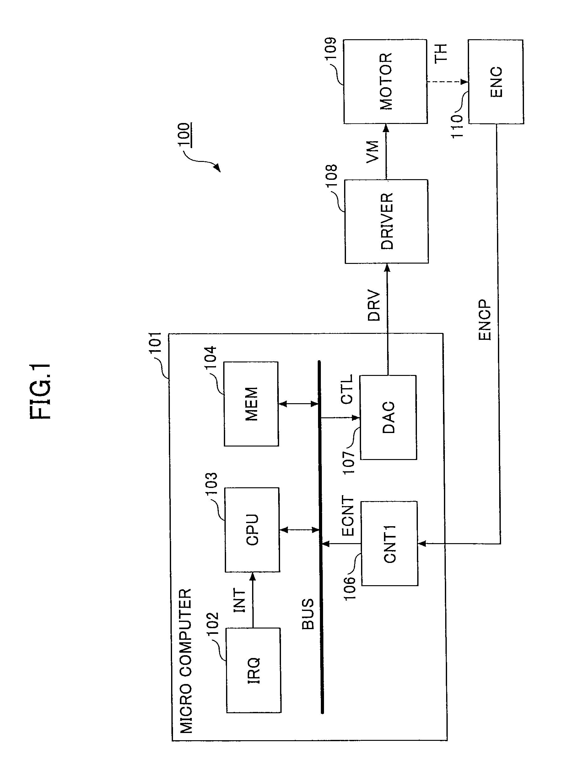
[0030]FIG. 1 is a schematic view illustrating a hardware configuration example of a motor controller 100 according to the first embodiment.

[0031]In FIG. 1, a microcomputer 101 is a general microcomputer equipped with a CPU 103, a memory 104 and input / output devices inside, which can execute prescribed tasks. A drive command signal DRV is output from the microcomputer 101 to a motor driver 108 connected to a motor 109.

[0032]The motor driver 108 outputs a drive voltage VM to the motor 109 in response to the drive command signal DRV output from the microcomputer 101. The drive command signal DRV may be indicated with a voltage or a pulse signal proportional to the voltage modulated with pulse width modulation (PWM), which are design alternatives. Similarly, the drive voltage VM may be indicated with a voltage or a PWM pulse.

[0033]The motor 109 generates a driving force in response to the drive voltage VM for rotary motion if the motor 109 is a rotary motor, or for linear motion if the ...

second embodiment

[0084]FIG. 5 is a schematic view illustrating a hardware configuration example of a motor controller according to the second embodiment.

[0085]FIG. 5 differs from FIG. 1 in that a counter 105 is newly added for counting a target pulse signal TGTP from an external device to output a count value XCNT. Namely, a mechanism is added to receive as input a target pulse signal from an external device. An explanation is omitted for the elements that have the same reference numerals as in FIG. 1 because these elements have the same functions.

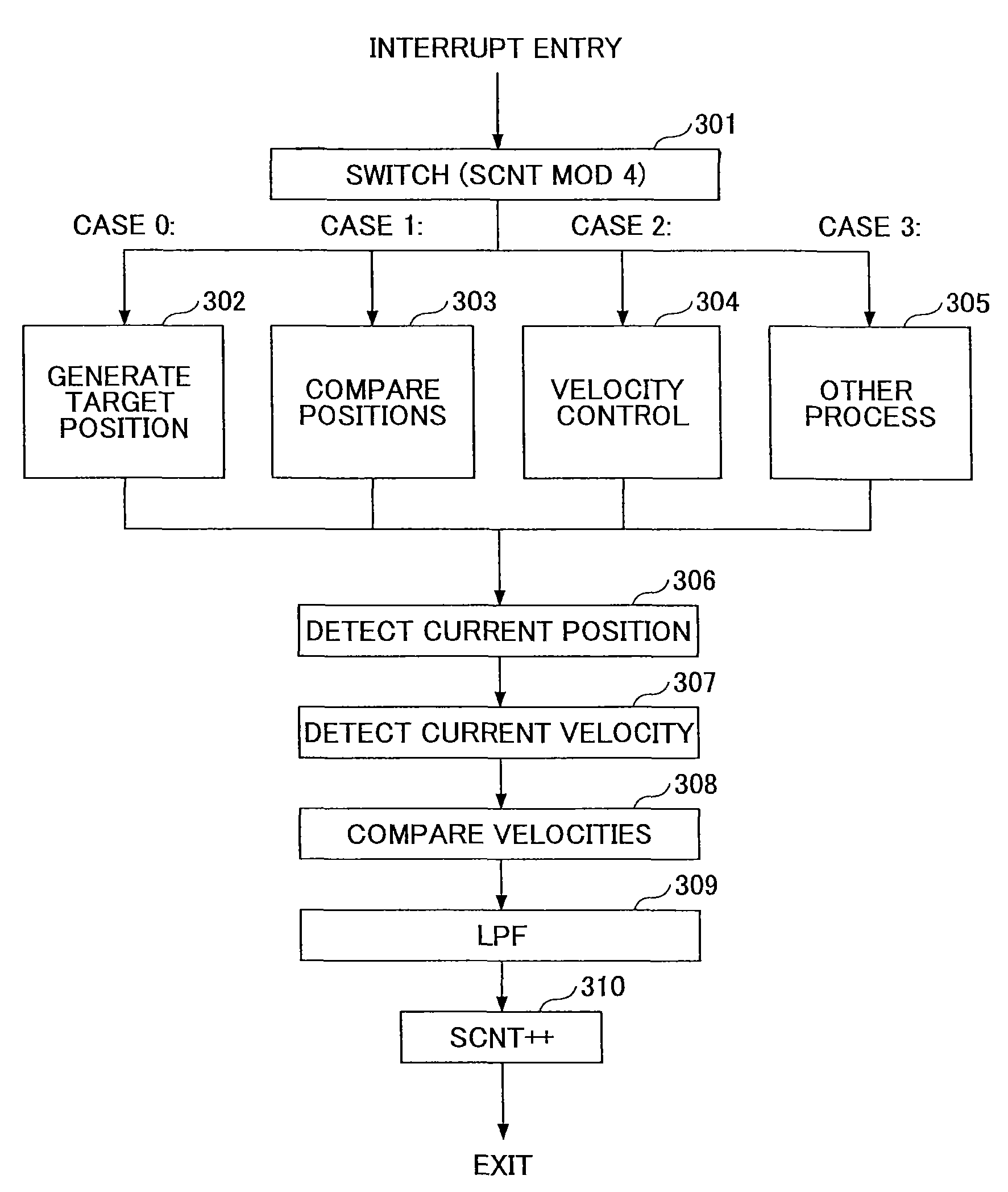
[0086]FIG. 6 is a signal flow diagram illustrating operations executed on the microcomputer 101 according to the second embodiment.

[0087]A generate-target-position operation 208 generates a target position XTGT by reading a count value XCNT that counts a target pulse signal TGTP from the external device. The sampling frequency of this operation is FS / 4. Namely this operation is executed at every fourth time an interrupt is activated.

[0088]A explanation of ...

third embodiment

[0092]FIG. 8 is a signal flow diagram illustrating operations executed on the microcomputer 101 according to the third embodiment. The hardware configuration in the third embodiment is the same as in the second embodiment shown in FIG. 5.

[0093]In FIG. 8, a generate-target-velocity operation 210 differentiates a target position XTGT output by the generate-target-position operation 208 to output a second target velocity VTGT2. Specifically, the generate-target-velocity operation 210 outputs the second target velocity VTGT2 by taking the difference between the target position XTGT at the current interrupt and the target position Z_XTGT at the previous interrupt.

[0094]It is preferable that the second target velocity VTGT2 has the same unit as the current velocity VDET output by the detect-current-velocity operation 204. The current velocity VDET is generated at every interrupt with the sampling frequency FS, while the generate-target-velocity operation 210 operates at every fourth inter...


PUM


Abstract

A motor controller receiving as input an encoder signal changing in response to a driving position of a motor, outputting a motor driving command in response to the encoder signal to control at least one of the driving position or a driving velocity of the motor, includes an interrupt processing section to execute interrupt operations every prescribed interrupt cycle, a low-frequency processing section to selectively execute a subset of the interrupt operations every prescribed number of the interrupt cycles, and a high-frequency processing section to execute another subset of the interrupt operations every prescribed interrupt cycle, wherein the high-frequency processing section executes at least an operation to detect the driving position indicated by the encoder signal, wherein the low-frequency processing section executes at least an operation to generate the motor driving command.

Description

BACKGROUND OF THE INVENTION[0001]1. Field of the Invention[0002]The disclosures herein generally relate to a technology to control velocity and position of a motor.[0003]2. Description of the Related Art[0004]Motors are widely used for moving objects such as sheets for sheet conveyance control in a printer, heads for head-positioning control in a disc storage device, etc. To control the position and the velocity of an object that is to be moved by the motor, a position sensor and / or a velocity sensor may be attached to the motor shaft or the object to be moved. A signal from the sensor is used for comparing the target position and / or velocity with the sensed current position and / or velocity, to feedback-control a motor drive quantity of the object.[0005]To execute such feedback control, digital control is widely used where a microcomputer, which is equipped with a CPU (Central Processing Unit), a memory and input / output ports and the like, sample sensor signals periodically and outp...

Claims


Application Information

Patent Timeline
Patent Type & Authority Patents(United States)
IPC IPC(8): H02P21/00G05B21/02H02P29/00
CPCG05B21/02G05B15/02G05D3/203
Inventor SUZUKI, HARUYUKIMURATA, TAKUYA
Owner RICOH KK
Why Eureka
Try Eureka