Low-pressure plasma system with sequential control process

a plasma system and sequential control technology, applied in the direction of electrical equipment, basic electric elements, electric discharge tubes, etc., can solve the problems of increasing the risk that a user of the low pressure plasma system actuates the mechanical switches in the incorrect sequence, and the general use of contactors on the fully automatic controller is therefore complex and cost-intensive, so as to achieve significant safety and procedural stability of the low pressure plasma system

Active Publication Date: 2017-08-22
DIENER CHRISTOF HERBERT
View PDF22 Cites 0 Cited by
  • Summary
  • Abstract
  • Description
  • Claims
  • Application Information

AI Technical Summary

Benefits of technology

[0021]The pressure ratios in the treatment chamber of the low pressure plasma system can be controlled by means of a time measurement. By way of example, the process step 1 (pumping out the treatment chamber) can be performed for a specific time period in order to ensure that a desired base pressure is achieved. It is therefore not mandatory to provide a pressure measuring device in the low pressure plasma system. However, the low pressure plasma system can be controlled in a precise manner by means of a pressure measuring electric circuit having a pressure measuring device, wherein the sequential switching element is embodied so as to interrupt and to close the pressure measuring electric circuit, wherein the pressure measuring electric circuit is closed in the switching positions 1 to 3, and also in particular in the switching positions 4 and / or 5. By means of the pressure measuring device, the user can precisely monitor the pressure prevailing in the treatment chamber.
[0022]The user can make the “further switching” of the sequential switching element dependent upon the pressure display of the pressure measuring device. In a preferred embodiment of the invention, the pressure measuring device is in contrast embodied for the purpose of transmitting a first enable signal to the gas supply valve to enable same and / or to the plasma generator in order to enable same. In this case, the subsequent process step can be prevented from being performed if the user further switches the sequential switching element “too early”, in other words if a “further switching” occurs without the necessary gas pressure ratios in the treatment chamber being present. As a consequence, the safety and the procedural stability of the low pressure plasma system is significantly increased.
[0024]The controller can furthermore comprise a heater electric circuit having a heating system, wherein the sequential switching element is embodied so as to interrupt and to close the heater electric circuit, wherein the heater electric circuit is closed in the switching position 3 (plasma treatment process). It is possible by means of the heating system to bring the component to an increased temperature during the plasma treatment process. The heater electric circuit can be closed in a further switching position or in multiple further switching positions in order to render it possible to preheat or reheat the component.
[0029]The controller of the low pressure plasma system can furthermore comprise a safety electric circuit having a safety switch, in particular a door switch of the treatment chamber, wherein the sequential switching element is embodied so as to interrupt and to close the safety electric circuit, wherein the safety electric circuit is closed in the switching positions 1 to 3 and also in particular in the switching positions 4 and / or 5. The safety electric circuit can be embodied so as to interrupt the processes that are performed in the low pressure plasma system. In particular, it is possible to disconnect the gas supply and the plasma generator by means of the safety electric circuit if the door of the treatment chamber is open. The safety electric circuit is used in particular to switch off the plasma generator in order to avoid a user receiving an electric shock. The safety electric circuit is in particular advantageous if the treatment chamber is not a glass chamber.
[0034]The rotary switch can merely be embodied as rotatable in one direction in order to entirely rule out an error in operating the low pressure plasma system. As an alternative thereto, it is possible that the rotary switch can be rotated in both directions. This is particularly advantageous if the controller comprises a ventilation process electric circuit having a ventilation valve. In this case, the rotary switch can be brought into the ventilating position by means of rotating in the “opposite direction” in order to ventilate the treatment chamber without having to perform a complete plasma treatment process.

Problems solved by technology

However, it is disadvantageous that generally contactors have to be used on the fully automatic controllers in order to connect the high supply voltages for the low pressure plasma system, in particular the plasma generator, to the controller.
A fully automatic controller is therefore accordingly complex and cost-intensive.
Although a low pressure plasma system having a controller of this type can be embodied in a simple and cost-effective manner, there is however the increased risk that a user of the low pressure plasma system actuates the mechanical switches in the incorrect sequence.
This risk is present in particular in the case of untrained users of the low pressure plasma system.
If by way of example the treatment chamber is ventilated, as long as the pump is still running, the oil consumption of the pump increases considerably.
Furthermore, the process of controlling the low pressure plasma system by means of actuating individual mechanical switches is uncomfortable for the user.

Method used


Image

  • Low-pressure plasma system with sequential control process
  • Low-pressure plasma system with sequential control process
  • Low-pressure plasma system with sequential control process

Examples


Embodiment Construction

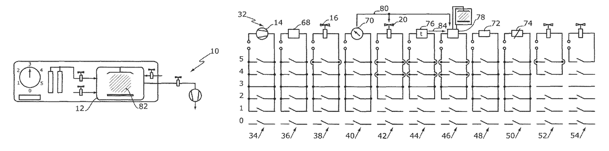
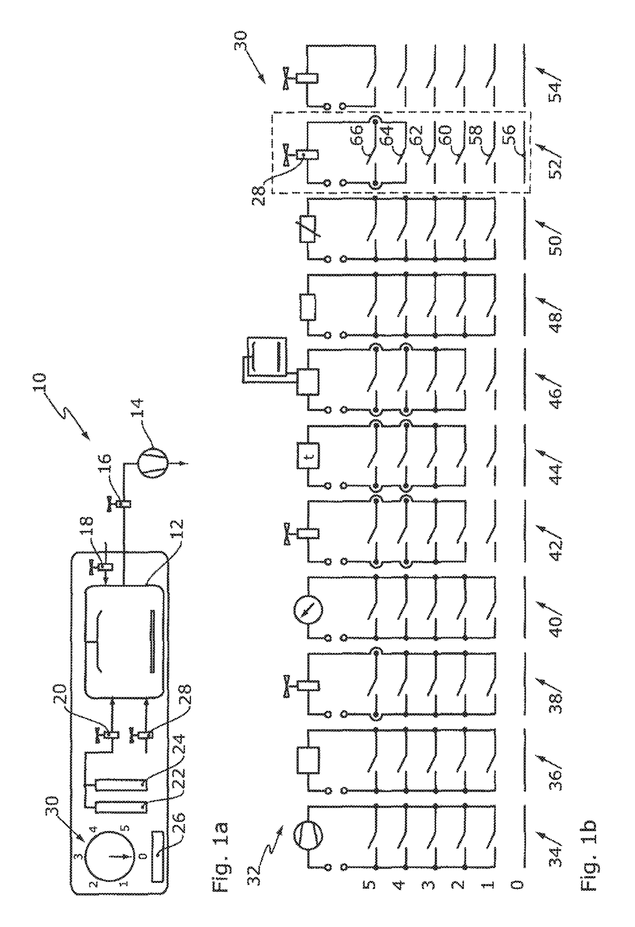
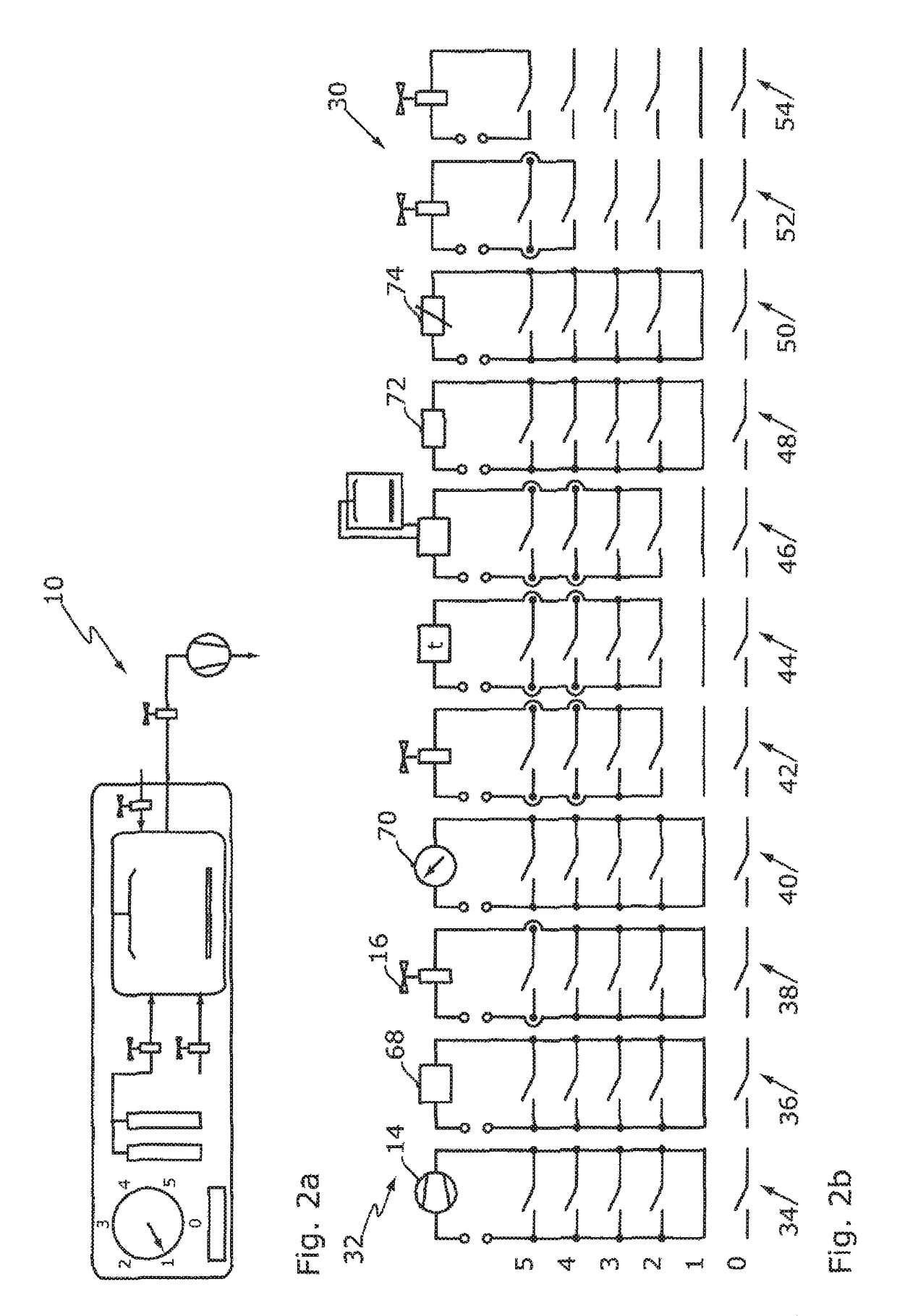
[0050]FIG. 1a illustrates a low pressure plasma system 10 in accordance with the invention. The low pressure plasma system 10 is illustrated in a heavily schematic manner. The low pressure plasma system comprises a treatment chamber 12 that can be at least in part evacuated by means of a pump 14. The pump 14 is connected in a fluid manner by way of a pump valve 16 to the treatment chamber 12. Consequently, in the case of a switched-on pump 14 and an opened pump valve 16 the treatment chamber 12 can be at least in part evacuated. The pump valve 16 is preferably embodied in the form of an angle valve.

[0051]A ventilation valve 18 is provided in order to ventilate the treatment chamber 12. A process gas can be admitted into the treatment chamber 12 by way of a gas supply valve 20. The process gas can be ambient air. As an alternative or in addition thereto, one or multiple gases can be admitted into the treatment chamber 12 as the process gas. In order to admit different gases into the ...


PUM


Abstract

The low pressure plasma system includes a treatment chamber which is pumped out in a first process step by means of a pump. In a second process step a gas supply valve is opened in order to achieve a defined gas composition in the treatment chamber at low pressure. In a third process step a plasma generator is switched on in order to ignite a plasma in the treatment chamber. In a fourth process step a flushing valve can be opened in order to flush the treatment chamber. In a fifth process step the treatment chamber can be ventilated by way of a ventilation valve. The sequential switching element can be a rotary switch and include a zero switching position where the low pressure plasma system is off. The sequential switching element renders possible a simple embodiment of the low pressure plasma system and its intuitive operation.

Description

CROSS-REFERENCE TO RELATED APPLICATIONS[0001]This continuation application claims priority to PCT / EP2015 / 056636 filed on Mar. 26, 2015, which has published as WO 2015 / 144848 A1, and also to German application number 10 2014 205 695.0 filed on Mar. 27, 2014, the entire contents of which are fully incorporated herein with these references.DESCRIPTION[0002]Field of the Invention[0003]The invention relates to a low pressure plasma system having a treatment chamber that can be at least in part evacuated, a gas supply valve, a plasma generator and a controller, wherein the controller comprises a vacuum electric circuit, a gas supply electric circuit and a plasma electric circuit, wherein the vacuum electric circuit controls a pump, which can be connected to the low pressure plasma system, and / or a pump valve of the low pressure plasma system, the gas supply electric circuit controls the gas supply valve and the plasma electric circuit controls the plasma generator.[0004]Background of the ...

Claims


Application Information

Patent Timeline
Patent Type & Authority Patents(United States)
IPC IPC(8): H01J37/32H01J37/18H01J37/244
CPCH01J37/32449H01J37/18H01J37/244H01J37/32009H01J37/32825H01J37/32926H01J2237/186
Inventor DIENER, CHRISTOF-HERBERT
Owner DIENER CHRISTOF HERBERT
Why Eureka
Try Eureka