Control of synchronous electrical machines

a synchronous motor and electrical machine technology, applied in the direction of dynamo-electric machines, single motor speed/torque control, synchronous motor starters, etc., can solve the problems of difficult starting of such motors, limited control of starting direction and torque, and difficulty in determining the starting direction of synchronous motors

Active Publication Date: 2010-08-19
WELLINGTON DRIVE TECHNOLOGIES
View PDF14 Cites 18 Cited by
  • Summary
  • Abstract
  • Description
  • Claims
  • Application Information

AI Technical Summary

Benefits of technology

[0020]Preferably the invention includes maintaining the rotor at a synchronous rotational rate once accelerated.
[0021]Preferably the invention includes initi

Problems solved by technology

Starting such motors is difficult since there is no unidirectional starting torque unless the motor speed is close to the synchronous speed in other words unless synchronous speed is low.
Examples of the latter include various clutches and impulse starters although a feature common to many is a difficulty in determining a starting direction for the synchronous motor, which wi

Method used


Image

  • Control of synchronous electrical machines
  • Control of synchronous electrical machines
  • Control of synchronous electrical machines

Examples


Embodiment Construction

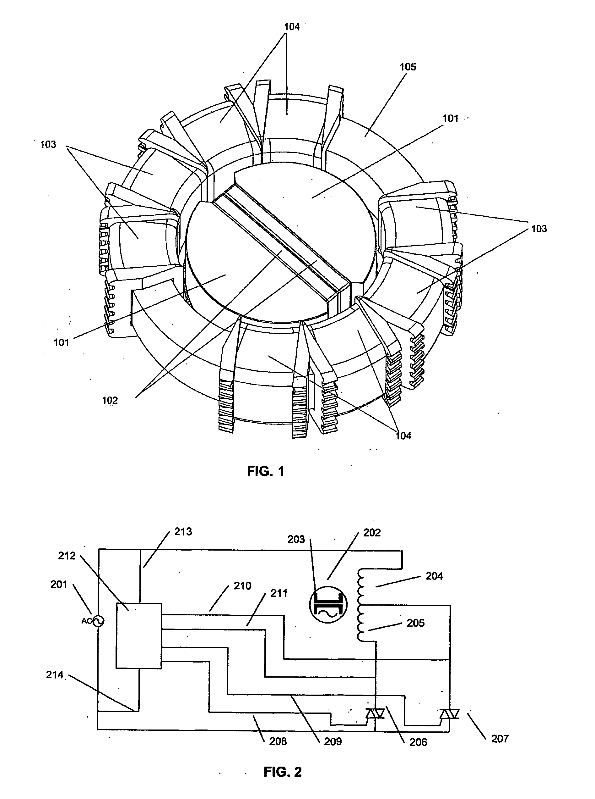
[0045]Referring now to FIG. 1 a synchronous motor consists generally of a rotor with pole pieces 101 and magnets 102, the axle shaft and driven connection of the rotor not being shown.

[0046]Stator 102 consists of a back iron 105, which is a toric magnetic element such as laminated steel; and wire wound bobbins 103, 104 where the bobbins form a winding on each pole of the motor, the bobbins forming a first winding of bobbin 103 and a second winding of bobbins 104, and the windings in total do not subtend the full circumference of the stator. The windings on the bobbins on each side consist typically of a single wire continuously wound along all four bobbins, but extending to a tap point located in the grooves on the bobbin cheek. There may be a tap point between each pair of bobbins or only one tap point may be present located between bobbins 103, 104. Typically the windings on each pole of a single phase machine may subtend from 120 to 135 degrees.

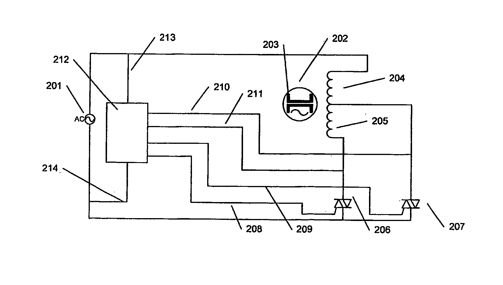
[0047]A single phase AC supply is c...


PUM


Abstract

A synchronous motor having phase windings which are split or tapped and in which the conduction angle of the applied alternating current is varied at one or more taps to allow the motor to start in a controlled direction and be torque controlled to synchronous speed.

Description

TECHNICAL FIELD[0001]The invention generally relates to alternating current driven synchronous motors.[0002]More particularly the invention relates to controlling alternating, current (AC) driven synchronous motors.BACKGROUND ART[0003]A synchronous motor may be defined as either a motor which has a running speed which is exactly proportional to an AC supply frequency or as a motor which is driven by waves of current synchronous with the motor back EMF. This latter definition includes at least some AC supplied brushless DC motors locked by electronic or other control to the AC supply for efficiency reasons.[0004]AC driven synchronous motors are an efficient and well known method of powering machines requiring a constant speed drive, since the motor is locked to a rotational rate which is dependent on the driving frequency. Starting such motors is difficult since there is no unidirectional starting torque unless the motor speed is close to the synchronous speed in other words unless s...

Claims


Application Information

Patent Timeline
IPC IPC(8): H02P6/08
CPCH02P1/22H02P1/46H02P1/52H02P23/0072H02P6/20H02P6/22H02P6/182H02P23/24
Inventor WILKINSON, JAMIE JON AORANGI
Owner WELLINGTON DRIVE TECHNOLOGIES
Why Eureka
Try Eureka