Computer implemented method to display technical data for monitoring an industrial installation

a technology of industrial installations and computer implementation, which is applied in the direction of testing/monitoring control systems, process and machine control, instruments, etc., can solve the problems of limiting the number of users, unable to extract all the information hidden in the acquired data, and unable to optimize or increase production, so as to improve the access to monitoring information, quick retrieve more detailed information, and improve the effect of monitoring

Active Publication Date: 2010-08-19
ABB (SCHWEIZ) AG
View PDF14 Cites 5 Cited by
  • Summary
  • Abstract
  • Description
  • Claims
  • Application Information

AI Technical Summary

Benefits of technology

[0009]According to another embodiment of the present invention an improvement is provided in the form of an improved method to generate a holographic image of an industrial installation or part thereof including information about an event or an alarm comprising the step of mapping the one of the one or more points which has been identified to one or more personnel located at an equipment, process section or part thereof in said industrial installation. This embodiment has the advantage of quickly and efficiently showing whereabouts on an oil platform or in another industrial installation an operator or engineer is located, which facilitates locating and / or treating or evacuating an operator in a problem situation.
[0016]An advantage is the generation of an improved overview of a current state of a given site and a 3-D interface through which to quickly retrieve more detailed information on selected events or objects. The invention allows an unlimited number of viewers to collaborate around the same hologram. This creates a working environment in which all users have the same hologram no matter location, and with different expertise.
[0017]Another advantage is the provision of position information for optimising or increasing production, by improved access to monitoring information and for real-time interaction between involved activities and disciplines, e.g. by users monitoring compressors or wells from land, and by contact with users or experts in the field if matters requiring action are discovered. The use of the invention is advantageous for eg interaction rooms used to support work processes between land and sea and between operator and supplier. This is in part because the invention provides an interface that promotes improved user perception of the site, the layout of relevant equipment or sections and the current state. It also supports efficient collaboration, both local and remote.
[0019]A further advantage is reduced operating and maintenance costs at the industrial installation which may be located, as in the case of an oil platform, such that it is time consuming, difficult or dangerous to access, by, with the aid of an embodiment of the invention enabling:Condition- and campaign-based maintenanceTransferal of administrative, surveillance, management and reviewing activities onshoreReduced usage of experts offshoreOnshore remote monitoringImproved efficiency for monitoring and analysis functionsNew ways of supporting the fields by centralising tasks, cross-field coordination and specialising service supplies to a larger degree

Problems solved by technology

A problem is that users are often not able to extract all the information that is hidden in the acquired data, because in part, the amount of process data is enormous.
Use of desktop screens also limits the numbers of users and therefore hinders collaboration possibilities between local and / or remote users.

Method used


Image

  • Computer implemented method to display technical data for monitoring an industrial installation
  • Computer implemented method to display technical data for monitoring an industrial installation
  • Computer implemented method to display technical data for monitoring an industrial installation

Examples


Embodiment Construction

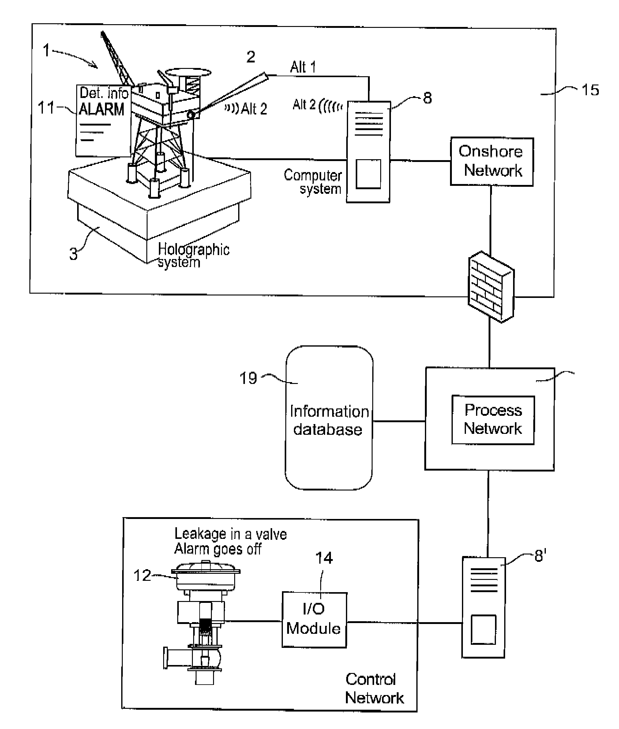
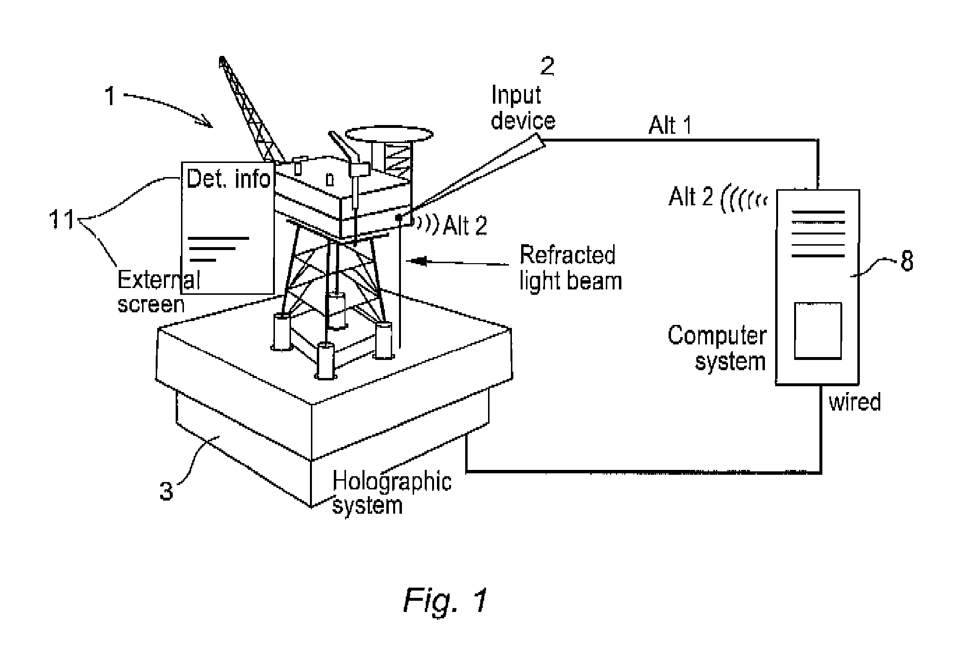
[0029]FIG. 1 shows an exemplary example of an embodiment of the invention. The figure shows a holographic system 3 for producing holographic images, and a holographic display 1 of an oil production platform. A pointer device 2 is shown positioned for interaction with the holographic image 1. The pointer 2 is shown here connected by a wire or wirelessly to a computer 8 which is also connected to the holographic system 3. A separate display, an external graphic screen 11 is schematically positioned adjacent the holographic image 1.

[0030]The system for carrying out the method comprises then a holographic apparatus 3 which generates an holographic image 1, and the device may also comprise light refraction detectors (not shown) or other means which may register where on the holographic image 1 the user “touches”, and an input device 2 with which the user may interact with the holographic image and preferably a data server which constantly feeds the holographic apparatus with updated proc...


PUM


Abstract

A computer implemented method to display an industrial installation, which display may also display information about an event or an alarm in the installation. The method includes displaying an image which appears to the viewer to be a three dimensional holographic image including a view of the industrial installation. The image may also include one or more points in three dimensional space and which point or points are each mapped to a corresponding point or position in the industrial installation. A pointing device for actively indicating position on the image reflecting objects or positions in the installation is also described.

Description

TECHNICAL FIELD[0001]The invention concerns methods and systems for remote monitoring of process equipment and process objects in an industrial control system. In particular the invention relates to monitoring of processes in oil and gas installations, production platforms and processing facilities.TECHNICAL BACKGROUND[0002]Today, most industrial installations and production facilities have modern and effective systems for data acquisition and storage with eg fiber-optic communications, databases, and so on. A problem is that users are often not able to extract all the information that is hidden in the acquired data, because in part, the amount of process data is enormous. Even though historical data is easily available, the user may need assistance help to locate process segments behaving abnormally, to gather information about that, and to arrive at a diagnosis of a condition or status of a process or equipment.[0003]In the field of process control in industrial plants IT is used ...

Claims


Application Information

Patent Timeline
Patent Type & Authority Applications(United States)
IPC IPC(8): G05B23/02G06F3/048G06T15/00
CPCG05B23/0267
Inventor SKOURUP, CHARLOTTEBREEN, SIRIHALL, NICOLAS-ALEXANDER
Owner ABB (SCHWEIZ) AG
Why Eureka
Try Eureka