
Pseudo Multi-Domain Design for Improved Viewing Angle and Color Shift

Active Publication Date: 2010-08-19
APPLE INC
View PDF101 Cites 57 Cited by
  • Summary
  • Abstract
  • Description
  • Claims
  • Application Information

AI Technical Summary

Benefits of technology

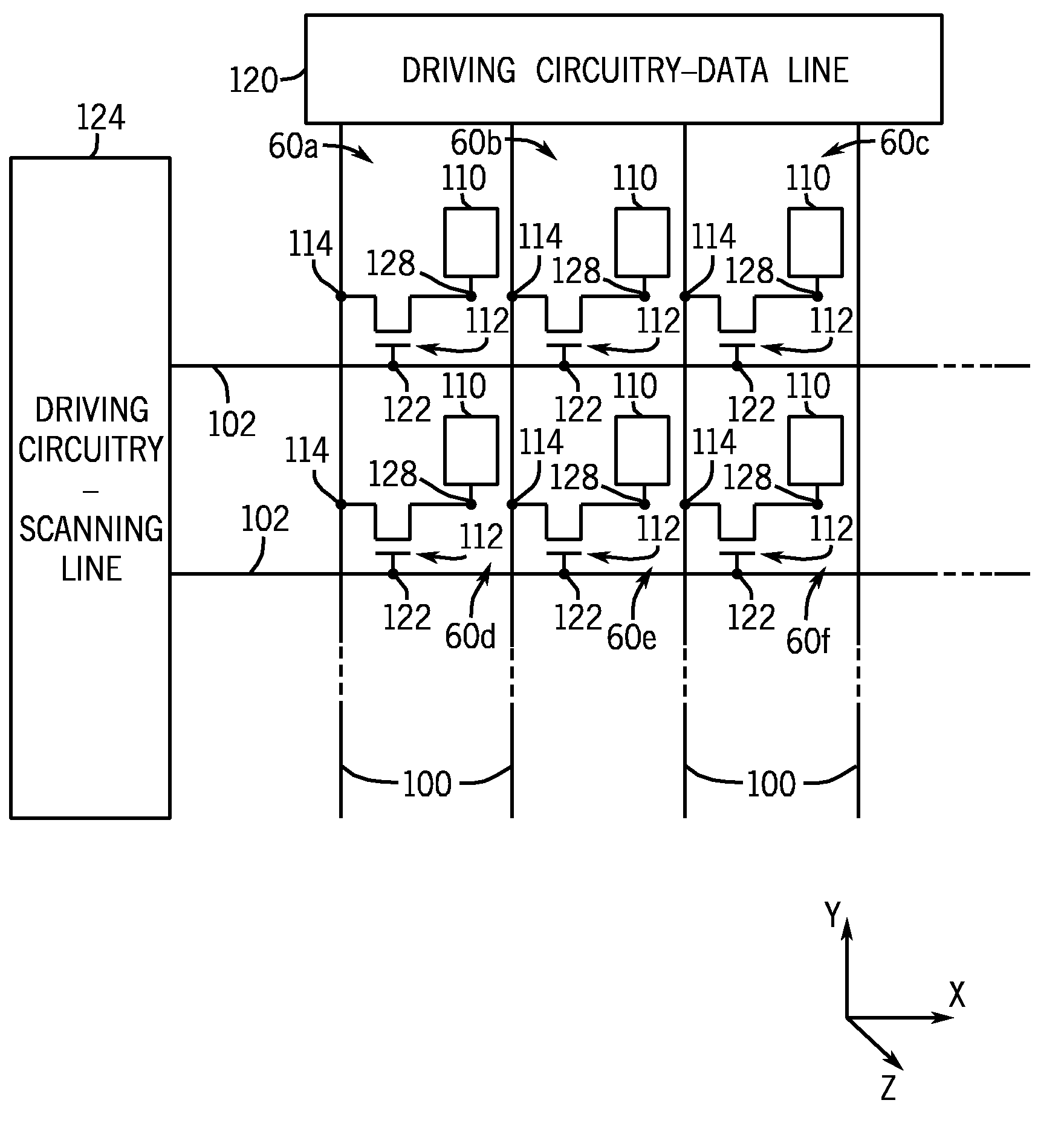
[0009]The present disclosure generally relates to single-domain electrode configurations that may be implemented in the unit pixels of a LCD device, such as a fringe field switching (FFS) LCD, to provide a “pseudo-multi-domain” effect, wherein the benefits of both conventional single-domain and multi-domain pixel configuration devices are retained. In accordance with aspects of the present technique, single-domain unit pixels are provided in order to maintain the relatively higher transmittance rates (as opposed to multi-domain transmittance rates) typical of conventional single-domain LCD panels (as opposed to multi-domain panel transmittance rates). In one embodiment, the single-domain unit pixels may be angled or tilted in differing directions with respect to a vertical axis of the LCD panel (e.g., y-axis) to provide an alternating and / or periodic arrangement of different-angled pixel electrodes along each scanning line, data line, or a combination of both scanning and data lines. In this manner, the transmittance rates of conventional single-domain LCD panels may be retained while providing for improved viewing angle and color shift properties typical of conventional multi-domain LCD panels.

Problems solved by technology

However, conventional single-domain pixel configurations generally offer poorer viewing angles and color shift properties compared to multi-domain configurations.
However, disclinations may result in light-transmissive portions of multi-domain unit pixels due to the differing directions of electrical fields.
Such disinclinations are particularly problematic in that they may block a portion of the light transmitted through the pixels, thus reducing the overall transmittance rate of the LCD panel.

Method used


Image

  • Pseudo Multi-Domain Design for Improved Viewing Angle and Color Shift
  • Pseudo Multi-Domain Design for Improved Viewing Angle and Color Shift
  • Pseudo Multi-Domain Design for Improved Viewing Angle and Color Shift

Examples


Embodiment Construction

[0023]One or more specific embodiments of the present disclosure will be described below. These described embodiments are only exemplary of the presently disclosed techniques. Additionally, in an effort to provide a concise description of these exemplary embodiments, all features of an actual implementation may not be described in the specification. It should be appreciated that in the development of any such actual implementation, as in any engineering or design project, numerous implementation-specific decisions must be made to achieve the developers' specific goals, such as compliance with system-related and business-related constraints, which may vary from one implementation to another. Moreover, it should be appreciated that such a development effort might be complex and time consuming, but would nevertheless be a routine undertaking of design, fabrication, and manufacture for those of ordinary skill having the benefit of this disclosure.

[0024]When introducing elements of vario...


PUM


Abstract

Aspects of the present disclosure relate to single-domain electrode configurations that may be implemented in the unit pixels of a LCD device, such as a fringe field switching (FFS) LCD, to provide a “pseudo-multi-domain” effect, wherein the benefits of both conventional single-domain and multi-domain pixel configuration devices are retained. In accordance with aspects of the present technique, single-domain unit pixels are angled or tilted in differing directions with respect to a vertical axis of the LCD panel (e.g., y-axis) to provide an alternating and / or periodic arrangement of different-angled pixel electrodes along each scanning line, data line, or a combination of both scanning and data lines. In this manner, the transmittance rates of conventional single-domain LCD panels may be retained while providing for improved viewing angle and color shift properties typical of conventional multi-domain LCD panels.

Description

BACKGROUND[0001]1. Technical Field[0002]Embodiments of the present disclosure relate generally to display devices and, more particularly, to liquid crystal display (LCD) devices.[0003]2. Description of the Related Art[0004]This section is intended to introduce the reader to various aspects of art that may be related to various aspects of the present techniques, which are described and / or claimed below. This discussion is believed to be helpful in providing the reader with background information to facilitate a better understanding of the various aspects of the present disclosure. Accordingly, it should be understood that these statements are to be read in this light, and not as admissions of prior art.[0005]Liquid crystal displays (LCDs) are commonly used as screens or displays for a wide variety of electronic devices, including such consumer electronics as televisions, computers, and handheld devices (e.g., cellular telephones, audio and video players, gaming systems, and so forth)...

Claims


Application Information

Patent Timeline
IPC IPC(8): G09G3/36
CPCG02F1/133512G02F1/133707G02F2001/134372G02F1/134363G02F2001/13373G02F1/134336G02F1/13373G02F1/134372G02F1/1343
Inventor XU, MINGCHEN, CHENGGU, MINGXIAZHONG, JOHN Z.GETTEMY, SHAWN ROBERTCHANG, SHIH CHANG
Owner APPLE INC
Learn More