Escapement governor, mechanical watch, pallet fork (incomplete) manufacturing method, and roller manufacturing method

a technology of escapement governor and manufacturing method, which is applied in the direction of photomechanical apparatus, instruments, and can solve the problems of limiting the thickness reduction of escapement governor, failing to exert the function of the escapement governor, and inability to achieve the complete reduction of etc., to achieve the effect of reducing the thickness of the pallet fork and the roller, reducing the inertia acting moment, and high precision

Active Publication Date: 2010-08-19
SEIKO INSTR INC
View PDF6 Cites 23 Cited by
  • Summary
  • Abstract
  • Description
  • Claims
  • Application Information

AI Technical Summary

Benefits of technology

[0029]According to this method, it is possible to form a roller through electroforming, so that there is no need to form the roller through cutting, thus making it possible to manufacture the roller with high pr

Problems solved by technology

On the other hand, in the technique as disclosed in “The Theory of Horology” mentioned above, there is used a single roller, and a reduction in the thickness of the peripheral structure thereof is achieved; however, since the safety pin is formed so as to protrude perpendicularly with respect to the pallet fork (incomplete), a reduction in the thickness of the pallet fork (complete) cannot be achieved, so that, also in this technique, there is a limit to a reduction in the thickness of the escapement governor.
However, the arrangement of the safety pin and the pair of entry horn and exit horn provided on the pallet fork (incomplete) as disclosed in JP-A-2004-309480 and of the passing hollow and the impulse pin of the single roller of “The Theory of Horology” mentioned above respectively corresponding thereto, is rather inappropriate, so that the pallet fork

Method used


Image

  • Escapement governor, mechanical watch, pallet fork (incomplete) manufacturing method, and roller manufacturing method
  • Escapement governor, mechanical watch, pallet fork (incomplete) manufacturing method, and roller manufacturing method
  • Escapement governor, mechanical watch, pallet fork (incomplete) manufacturing method, and roller manufacturing method

Examples


embodiment 1

Construction of the Escapement Governor

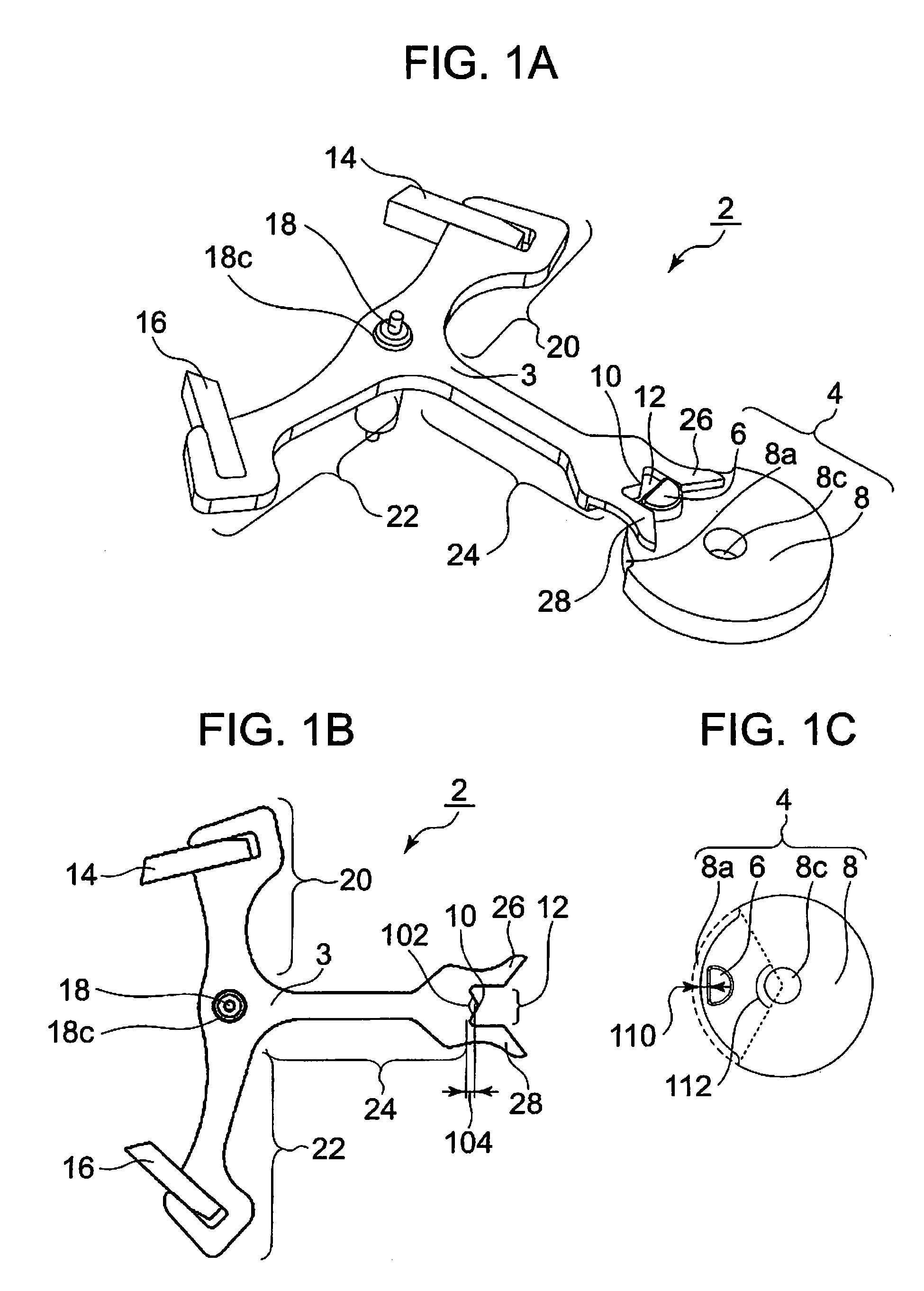
[0072]FIGS. 1A and 1B are diagrams illustrating an escapement governor equipped with a pallet fork (complete) 2 and a roller 4 according to Embodiment 1 of the present invention. FIG. 1A is a perspective view of the pallet fork (complete) 2 and the roller 4; FIG. 1B is a plan view of the pallet fork (complete) 2; and FIG. 1C is a plan view of the roller 4.

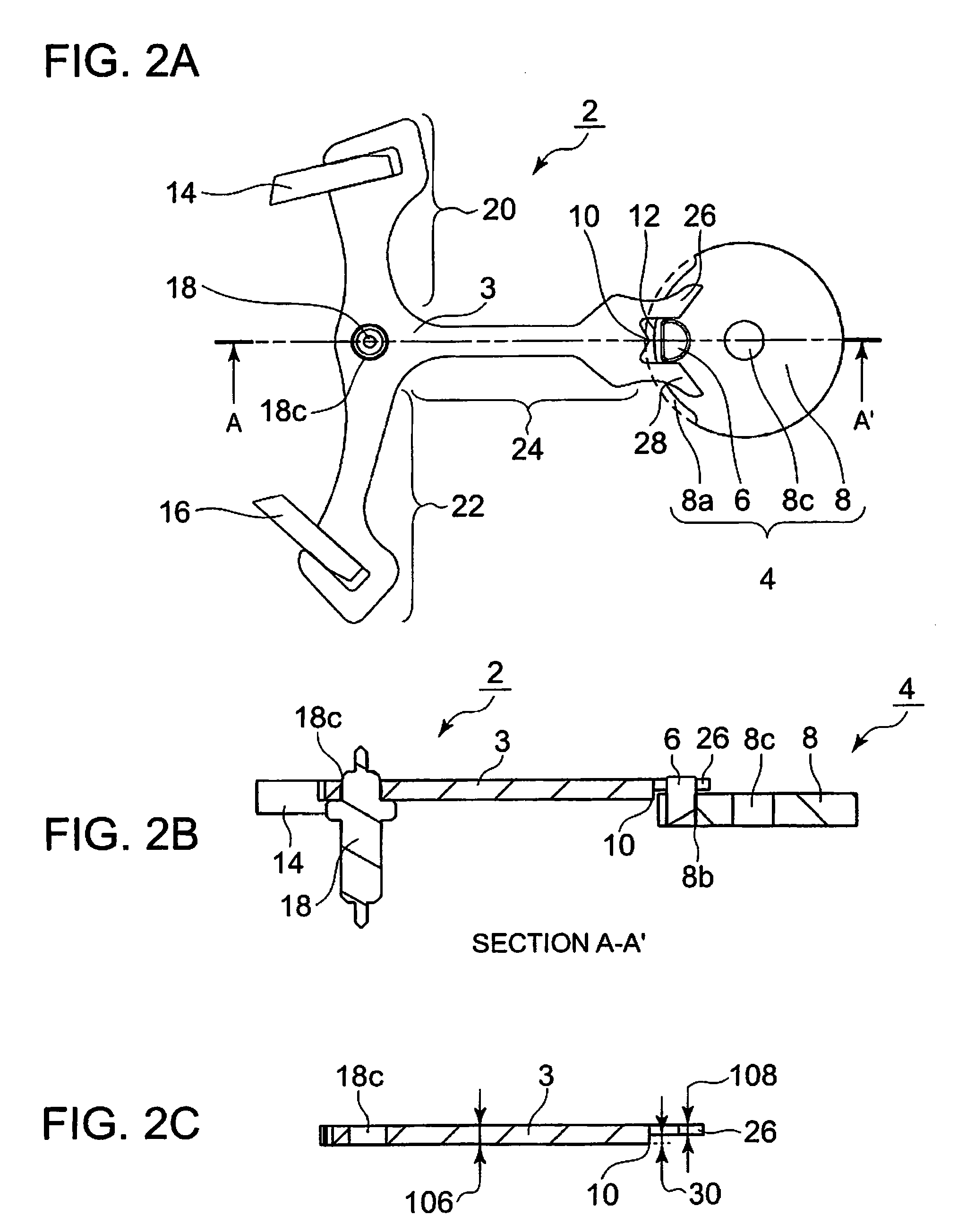
[0073]FIGS. 2A and 2B are diagrams illustrating the pallet fork (complete) 2 and the roller 4 of Embodiment 1 of the present invention. FIG. 2A is a plan view of the pallet fork (complete) 2 and the roller 4; FIG. 2B is a sectional view of the pallet fork (complete) 2 and the roller 4 taken along the segment AA′ of FIG. 2A; and FIG. 2C is a sectional view of a pallet fork (incomplete) 3 taken along the segment AA′ of FIG. 2A.

[0074]In FIGS. 1C and 2A, the broken line indicates the outer circumference of a roller table 8 as extended along a passing hollow 8a formed in the roller table 8.

[0075]In...

embodiment 2

[0135]FIG. 32 is a plan view illustrating a pallet fork (incomplete) 3a according to Embodiment 2 of the present invention. The portions of the pallet fork (incomplete) 3a that are the same as those of the pallet fork (incomplete) 3 of Embodiment 1 are to be indicated by the same reference numerals, so such reference numerals are omitted. The following description will center on the differences in configuration between the pallet fork (incomplete) 3a and the pallet fork (incomplete) 3 of Embodiment 1 of the present invention.

[0136]In the pallet fork (incomplete) 3a, the entry arm 20, the exit arm 22, and the lever 24 of the pallet fork (incomplete) 3 are provided with through-holes, such as holes 76a, 76b, 76c, 76d, 76e, 76f, 76g, and 76h. It does not necessarily mean that all of the entry arm 20, the exit arm 22, and the lever 24 of the pallet fork (incomplete) 3 are provided with a plurality of through-holes; the number and configuration of through-holes may be determined as appro...

embodiment 3

[0138]FIG. 33 is a plan view illustrating a pallet fork (incomplete) 3b according to Embodiment 3 of the present invention. The portions of the pallet fork (incomplete) 3b that are the same as those of the pallet fork (incomplete) 3 of Embodiment 1 are to be indicated by the same reference numerals, so such reference numerals are omitted. The following description will center on the differences in configuration between the pallet fork (incomplete) 3b and the pallet fork (incomplete) 3 of Embodiment 1 of the present invention.

[0139]In the pallet fork (incomplete) 3b, of both end portions of the lever 24 of the pallet fork (incomplete) 3, the end portion near the safety pin 10 and the pair of entry horn and exit horn 26, 28 has a width 24a which is, for example, not less than 1 time and not more than 2.5 times the width 24b of an intermediate portion between both end portions of lever 24. Since the safety pin 10 is not forced into it, the pallet fork (incomplete) 3 does not need a hol...


PUM


Abstract

Disclosed are an integrally molded type pallet fork (incomplete) with a safety pin and a roller table that are formed with high precision by a simple process, a thin escapement governor including the pallet fork (complete) and the roller table, and a method of manufacturing the pallet fork (complete) and the roller table. The pallet fork (complete) of the escapement governor includes a pair of entry horn and exit horn extending from the rotation axis of the pallet fork (complete) toward the rotation axis of a balance with hairspring and adapted to transmit the power of an escape wheel to an impulse pin; and a safety pin which is provided in a side surface of the pallet fork (complete) between the pair of entry horn and exit horn, which extends from the rotation axis of the pallet fork (complete) toward the rotation axis of the balance with hairspring, which is situated at a position nearer to the rotation axis of the pallet fork (complete) than the pair of entry horn and exit horn, which enters a passing hollow to thereby cause the pallet fork (complete) to make normal rotation or reverse rotation with respect to the rotation axis of the pallet fork (complete), and which abuts a portion of a roller other than the passing hollow to thereby prevent erroneous rotation of the pallet fork (complete); and the roller is formed in a single layer.

Description

RELATED APPLICATIONS[0001]This application claims priority under 35 U.S.C. §119 to Japanese Patent Application Nos. 2009-034325 filed on Feb. 17, 2009 and 2010-010351 filed on Jan. 20, 2010, the entire contents of which are hereby incorporated by reference.BACKGROUND OF THE INVENTION[0002]1. Field of the Invention[0003]The present invention relates to an escapement governor equipped with an escape wheel, a balance with hairspring, and a pallet fork transmitting the power of the escape wheel to the balance with hair spring (roller), and to a mechanical watch; further, the present invention relates to a method of manufacturing a pallet fork (incomplete) constituting the frame of a pallet fork (complete), and a method of manufacturing a roller used with a pallet fork (incomplete).[0004]2. Description of the Related Art[0005]There exists a club tooth lever type escapement governor for a mechanical watch. In a known construction of such an escapement governor, in assembling a pallet fork...

Claims


Application Information

Patent Timeline
IPC IPC(8): G04B15/00G03F7/20
CPCG04B15/14G03F7/0035
Inventor HIRAOKA, MASASHINIWA, TAKASHI
Owner SEIKO INSTR INC
Why Eureka
Try Eureka