

Method of capturing linear features along a reference-line across a surface for use in a map database
a technology of a reference line and a map database, which is applied in the field of producing linear features along a reference line across a surface for use in a map database, can solve the problems of more time and effort, complex algorithms, and more complex filters than filters for detecting vertical or horizontal, and achieve the effect of reducing the number of image lines and high accuracy position determination
- Summary
- Abstract
- Description
- Claims
- Application Information
AI Technical Summary
Benefits of technology
Problems solved by technology
Method used
Image

Examples
Embodiment Construction
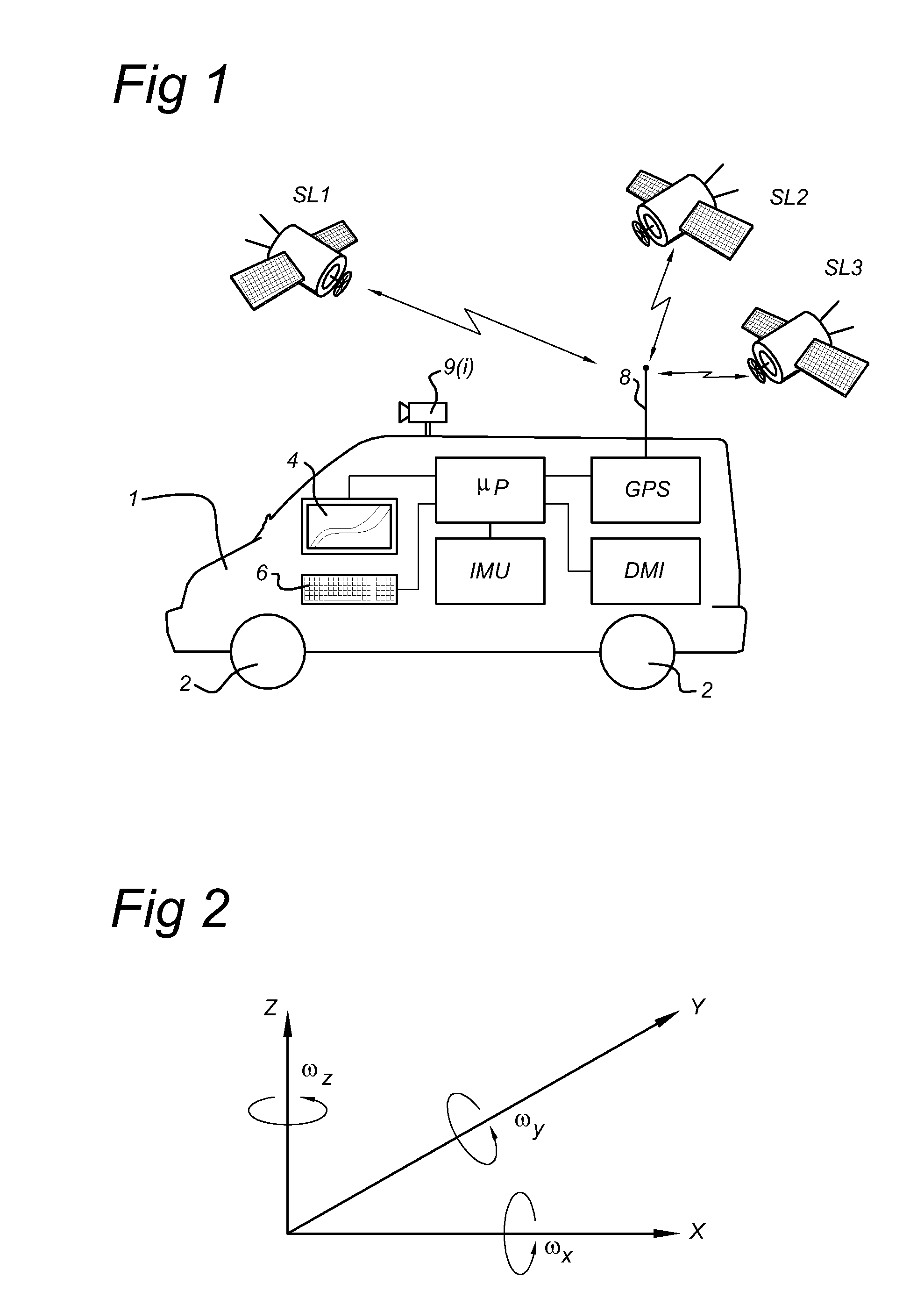
[0074]FIG. 1 shows a MMS system that takes the form of a car 1. The car 1 is provided with one or more cameras 9(i), i=1, 2, 3, . . . I. The looking angle or the one or more cameras 9(i) can be in any direction with respect to the driving direction of the car 1 and can thus be a front looking camera, a side looking camera or rear looking camera, etc. The viewing window(s) of the camera(s) 9(i) cover(s) the whole road surface in front the vehicle. Preferably, the angle between the driving direction of the car 1 and the looking angle of a camera is within the range of 45 degree-135 degree on either side. The car 1 can be driven by a driver along roads of interest.
[0075]The car 1 is provided with a plurality of wheels 2. Moreover, the car 1 is provided with a high accuracy position determination device. As shown in FIG. 1, the position determination device comprises the following components:
[0076]a GPS (global positioning system) unit connected to an antenna 8 and arranged to communica...
PUM
 Abstract
Description
Claims
Application Information