Method for optical measurement of the three dimensional geometry of objects

a three-dimensional geometry and optical measurement technology, applied in the field of optical measurement of the three-dimensional geometry of objects, can solve the problems of erroneous surface structure of the object being scanned, the two-dimensional patterns of the images pi cannot be correctly merged,

Active Publication Date: 2010-08-19
SIRONA DENTAL SYSTEMS
View PDF16 Cites 45 Cited by
  • Summary
  • Abstract
  • Description
  • Claims
  • Application Information

AI Technical Summary

Benefits of technology

[0035]One advantage of this method of the invention is that, unlike conventional methods, it corrects the errors that are caused by shaking movements of the hand-held scanning device. This is especially advantageous for dental intra-oral cameras, which are hand-held and used to generate 3D data sets of tooth surfaces. Camera-shake causes the resulting 3D images to show defects such as pointed or stepped structures, and the 3D scan must be repeated.
[0036]The overlapping of the common points allows the changes in position of the pattern caused by camera-shake to be identified and compensated for.
[0037]Another advantage is that the method of the invention makes on-the-fly measurement possible. The scanning device can be moved smoothly relatively to the object being scanned and the individual images scanned from different directions can be combined to form a complete 3D data set. It is thus not necessary to hold the scanning device still during an exposure. A sequence of exposures can be made without interruption while the scanning device is being moved relatively to the object.

Problems solved by technology

Since the change in the orientation between camera and object is, however, unknown, the two-dimensional patterns of the images Pi cannot be correctly merged to form a common 2-dimensional pattern of the overall image, which, for example, is chosen so as to be the same as the coordinate system of the first exposure.
When the relief data contained in the lines of the 2-dimensional patterns of the blurred individual images are merged to form a common 2-dimensional pattern, an erroneous surface structure of the object being scanned will be obtained.
The present problem is to provide a method for creating a three-dimensional image of an object being scanned, particularly for dental purposes, which produces a sufficiently accurate 3D model even if camera-shake takes place.

Method used


Image

  • Method for optical measurement of the three dimensional geometry of objects
  • Method for optical measurement of the three dimensional geometry of objects
  • Method for optical measurement of the three dimensional geometry of objects

Examples


Embodiment Construction

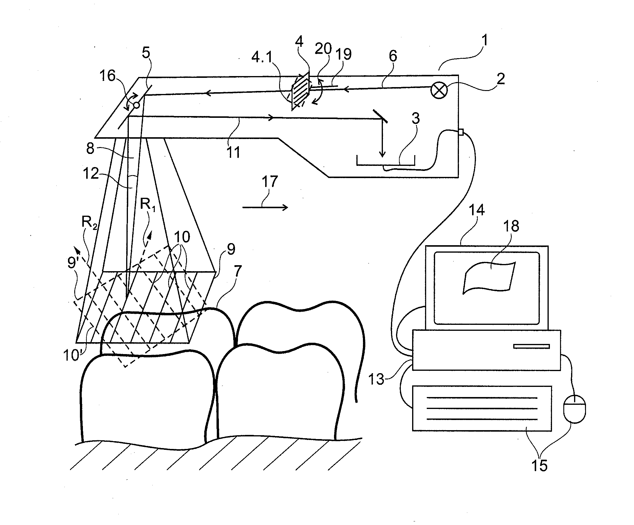
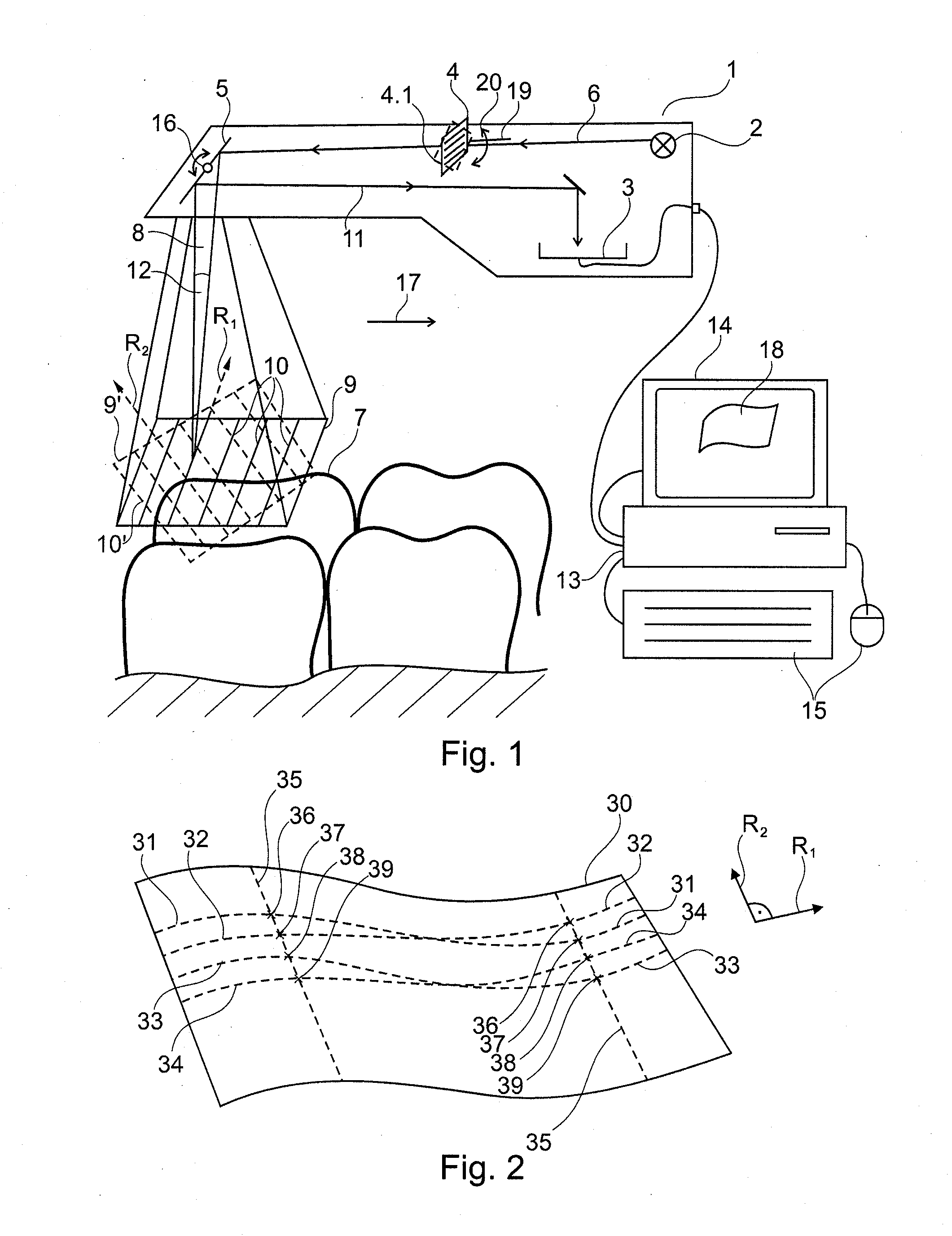
[0114]FIG. 1 shows an intraoral dental camera as scanning device 1, which is equipped with a light source 2, a sensor 3, a grid 4, and a pivoted mirror 5. The light source 2 emits a projected beam 6 that passes through the grid 4 and is directed by the pivoted mirror 5 onto the object 7, namely the surface of a tooth to be scanned. The grid 4 has a slit 4.1 that is perpendicular to the plane of triangulation 8, so that a structured pattern 9 comprising parallel stripes 10 is projected onto the surface of the object 7 to be scanned. The structured pattern 9 is only diagrammatically illustrated and does not represent the actual projection of light stripes 10 on the object 7 to be scanned. The projected beam 6 is reflected by the surface of the object 7 and is back-projected as a monitoring beam 11. The monitoring beam 11 is directed to the sensor 3 and detected thereby. The plane of triangulation 8 is defined by the projected beam 6 and the monitoring beam 11. The projected beam 6 enc...


PUM


Abstract

The invention relates to a method for optically scanning the three-dimensional geometry of an object by means of triangulation, in which a pattern (9, 9′) is projected onto the object (7) to be scanned in order to obtain a 3D data set, and the projected pattern (9, 9′) is recorded in an image (40, 41). In a first step for the production of at least one first image (40), a first pattern (9) is projected and in a second step for the creation of at least one further image (40), a further pattern (9′) deviating from the first as regards position or shape is projected onto the object (7) to be scanned and the image (41) is created. The first image (40) and the further image (41) comprise at least one common point (44). The 3D data acquired from the images (40, 41) are merged in a subsequent step on the basis of the 3D data of the at least one common point (44) such that the 3D data acquired from said images (40, 41) agree at least with reference to the 3D data of the common point (44) in the 3D data set.

Description

TECHNICAL FIELD[0001]The invention relates to a method for optical measurement of the three dimensional geometry of objects and is concerned with the problem of camera-shake induced in 3D data of scanned objects acquired using stripe projecting methods and with the task of 3D scanning when there is relative motion between the camera and the object when being scanned, particularly for dental purposes.PRIOR ART[0002]Digital design data for the computer-assisted production of dental prosthetic items without having to create the usual impression can be acquired by optically scanning one or more teeth in a patient's mouth.[0003]For such scanning, use is frequently made of measuring methods based on the principle of triangulation. Phase-shifting triangulation is disclosed in EP 0 160 797, in which a three dimensional data set is acquired from a sequence of images of a pattern which is displaced from image to image.[0004]With prior triangulation methods, a single straight stripe of light i...

Claims


Application Information

Patent Timeline
Patent Type & Authority Applications(United States)
IPC IPC(8): G06K9/52G01B11/24
CPCA61B5/0064A61B5/1077G01B11/2518G01B11/2513A61B5/4547
Inventor THIEL, FRANKPFEIFFER, JOACHIM
Owner SIRONA DENTAL SYSTEMS
Why Eureka
Try Eureka