Microporous polyolefin membrane, its production method, battery separator and battery

a microporous polyolefin and membrane technology, applied in the field of polyolefin membranes, can solve the problems of low pin puncture strength, manufacturing difficulties, and difficulty in obtaining high power output, and achieve the effects of good balance of permeability, heat-shrinkage resistance, and pin puncture strength

Active Publication Date: 2010-08-19
TORAY IND INC +1
View PDF6 Cites 27 Cited by
  • Summary
  • Abstract
  • Description
  • Claims
  • Application Information

AI Technical Summary

Problems solved by technology

However, the use of thick separators can lead to a relatively high internal electrical resistance of the battery, resulting in difficulty in obtaining high power output.
Thick separators for batteries of relatively low internal resistance can be produced by increasing the separator's porosity, but such microporous membranes are disadvantageous in that they can exhibit low pin puncture strength which can lead to manufacturing difficulties.
Although separators of relatively high porosity are generally desirable for use in HEV batteries, increasing separator porosity generally reduces the separator's heat shrinkage resistance, which can result in separators that are more easily broken when wound up, leading to short-circuiting between the battery's electrodes.

Method used


Image

  • Microporous polyolefin membrane, its production method, battery separator and battery

Examples


example 1

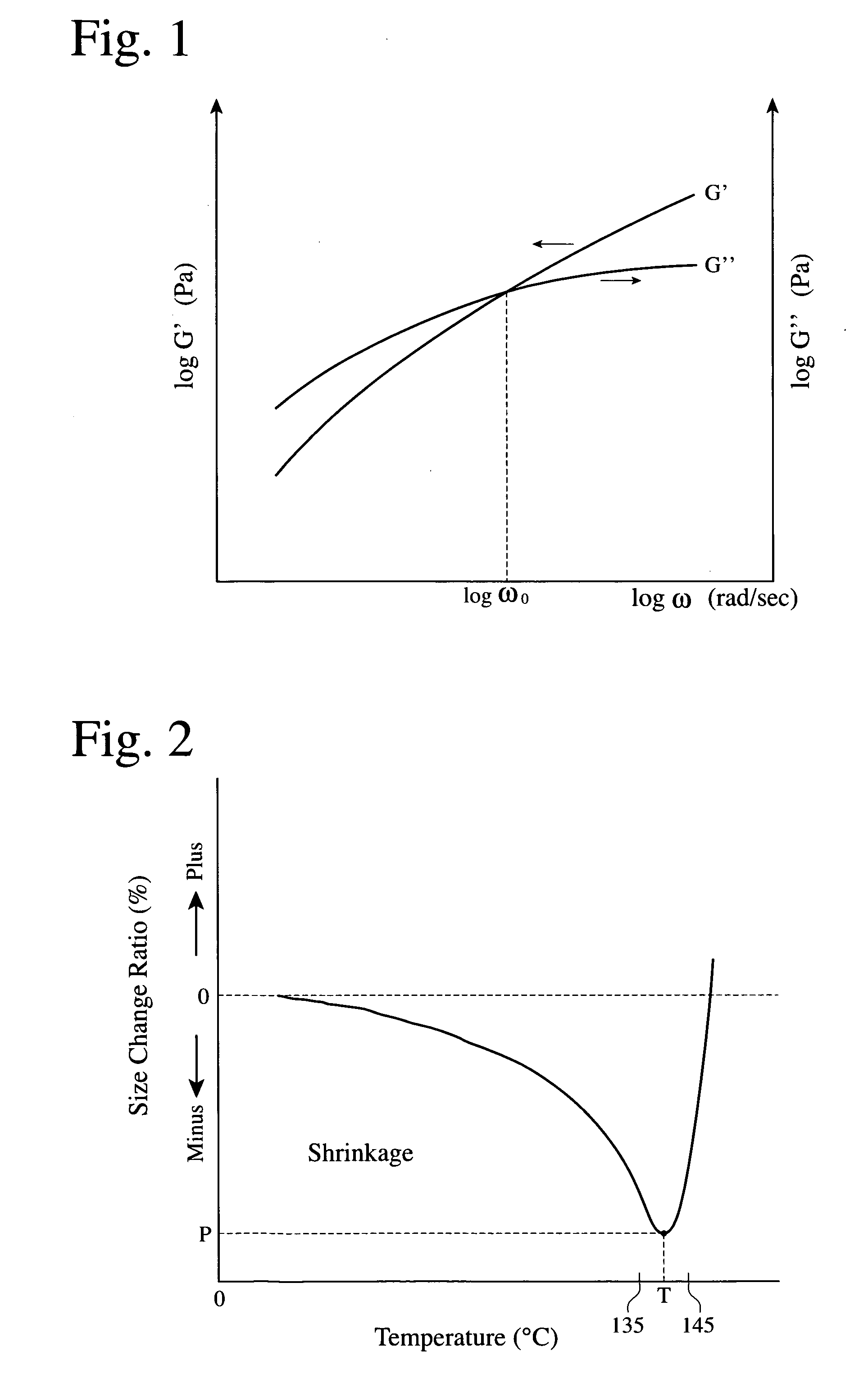
[0153]99.625 parts by mass of a polyethylene (PE) composition comprising 18% by mass of ultra-high-molecular-weight polyethylene (UHMWPE) having a weight-average molecular weight (Mw) of 2.5×10⁶, and 82% by mass of high-density polyethylene (HDPE) having Mw of 2.8×10⁵, were dry-blended with 0.375 parts by mass of tetrakis[methylene-3-(3,5-ditertiary-butyl-4-hydroxyphenyl)-propionate] methane as an antioxidant. The melt rheometry of the PE composition by RheoStress-300 (available from Haake) at 180° C. revealed that an angular frequency ω0, at which storage elastic modulus G′ and loss elastic modulus G″ were equal, was 0.114 rad / sec. The measurement of the same PE composition also revealed that it had a melting point of 135° C. and a crystal dispersion temperature Tcd of 90° C.

[0154]The Mws of UHMWPE and HDPE were measured by a gel permeation chromatography (GPC) method under the following conditions.[0155]Measurement apparatus: GPC-150C available from Waters Corporation,[0156]Column...

example 2

[0166]A microporous polyethylene membrane having an average thickness of 24.7 μm was produced in the same manner as in Example 1, except that the stretching temperature was 119.5° C., that the re-stretching conditions were a temperature of 122.5° C. and a magnification of 1.6 fold in a transverse direction, and that annealing was conducted at 122.5° C. such that the length in a transverse direction became 1.4 fold that before re-stretching.

example 3

[0167]APE composition comprising 30% by mass of UHMWPE and 70% by mass of HDPE was prepared. This PE composition had ω0 of 0.0343 rad / sec, a melting point of 135° C., and a crystal dispersion temperature Tcd of 100° C. A microporous polyethylene membrane having an average thickness of 25.6 μm was produced from this composition in the same manner as in Example 1, except that the concentration of a polyethylene solution was 23% by mass, that the re-stretching conditions were a temperature of 123° C. and a magnification of 1.6 fold in a transverse direction, and that annealing was conducted at 123° C. such that the length in a transverse direction became 1.4 times that before re-stretching.


PUM

PropertyMeasurementUnit
viscoelastic angular frequency ω0aaaaaaaaaa
temperatureaaaaaaaaaa

Abstract

The invention relates to a microporous membrane. The membrane can have an average thickness of 23 ?m or more, an air permeability in a range of about 20 sec / 100 cm3 to 100 sec / 100 cm3, a pin puncture strength of 2,450 mN or more, and a heat shrinkage ratio of 12% or less at 105° C. The membrane can be produced from a polyolefin solution made by combining a membrane-forming solvent and at least one polyolefin resin containing polyethylene having a viscoelastic angular frequency ??0#191 of at least about 0.01 rad / sec.

Description

FIELD OF THE INVENTION[0001]The invention relates to a polyolefin membrane having suitably well-balanced permeability, pin puncture strength and heat shrinkage resistance, a process for producing the microporous membrane, a battery separator formed by such a microporous polyolefin membrane, a battery comprising such a separator, and the use of such a battery.BACKGROUND OF THE INVENTION[0002]Microporous polyethylene membranes are mainly used as battery separators, particularly as separators for lithium batteries such as primary and secondary lithium ion batteries. Such batteries can be used to power electrical and electronic equipment such as mobile phones, notebook-type personal computers, etc. Recently, investigations have been conducted relating to the use of lithium secondary batteries as a power source for electric vehicles and hybrid cars. Batteries for hybrid electric vehicles (HEVs) such as hybrid cars need a relatively high power output which generally leads to the selection...

Claims


Application Information

Patent Timeline
Patent Type & Authority Applications(United States)
IPC IPC(8): H01M10/44B29C67/20B32B27/32B32B33/00H01M2/16H01M10/052H01M50/406H01M50/417H01M50/489H01M50/491
CPCC08J9/28C08J2201/03C08J2201/0502C08J2323/04Y10T29/49108H01M2/1653H01M10/052H01M10/30H01M10/345H01M2/145Y10T428/249993Y02E60/10Y02P70/50H01M50/417H01M50/406H01M50/491H01M50/489C08J5/18H01M50/403H01M50/411
Inventor KIMISHIMA, KOTARO
Owner TORAY IND INC
Why Eureka
Try Eureka