
High Precision Infusion Pumps

Active Publication Date: 2010-08-19
VTITAN
View PDF19 Cites 97 Cited by
  • Summary
  • Abstract
  • Description
  • Claims
  • Application Information

AI Technical Summary

Benefits of technology

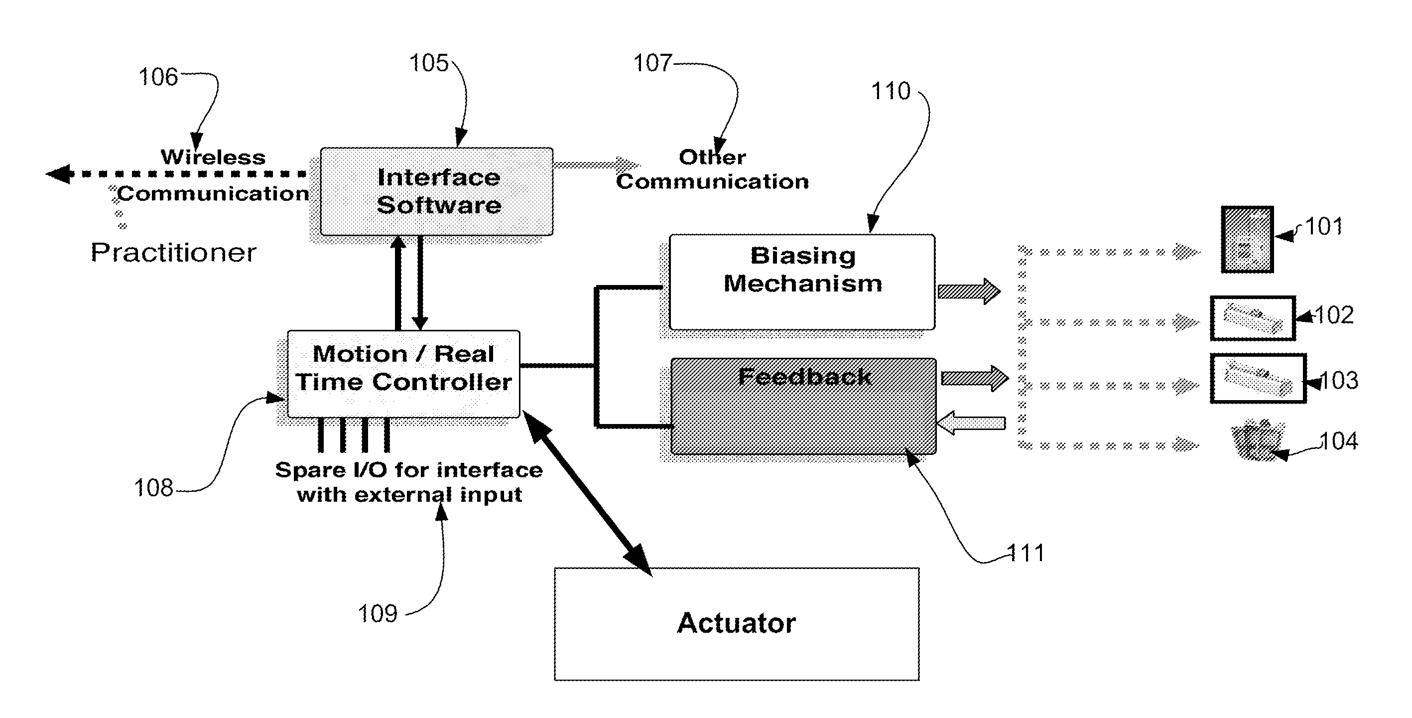
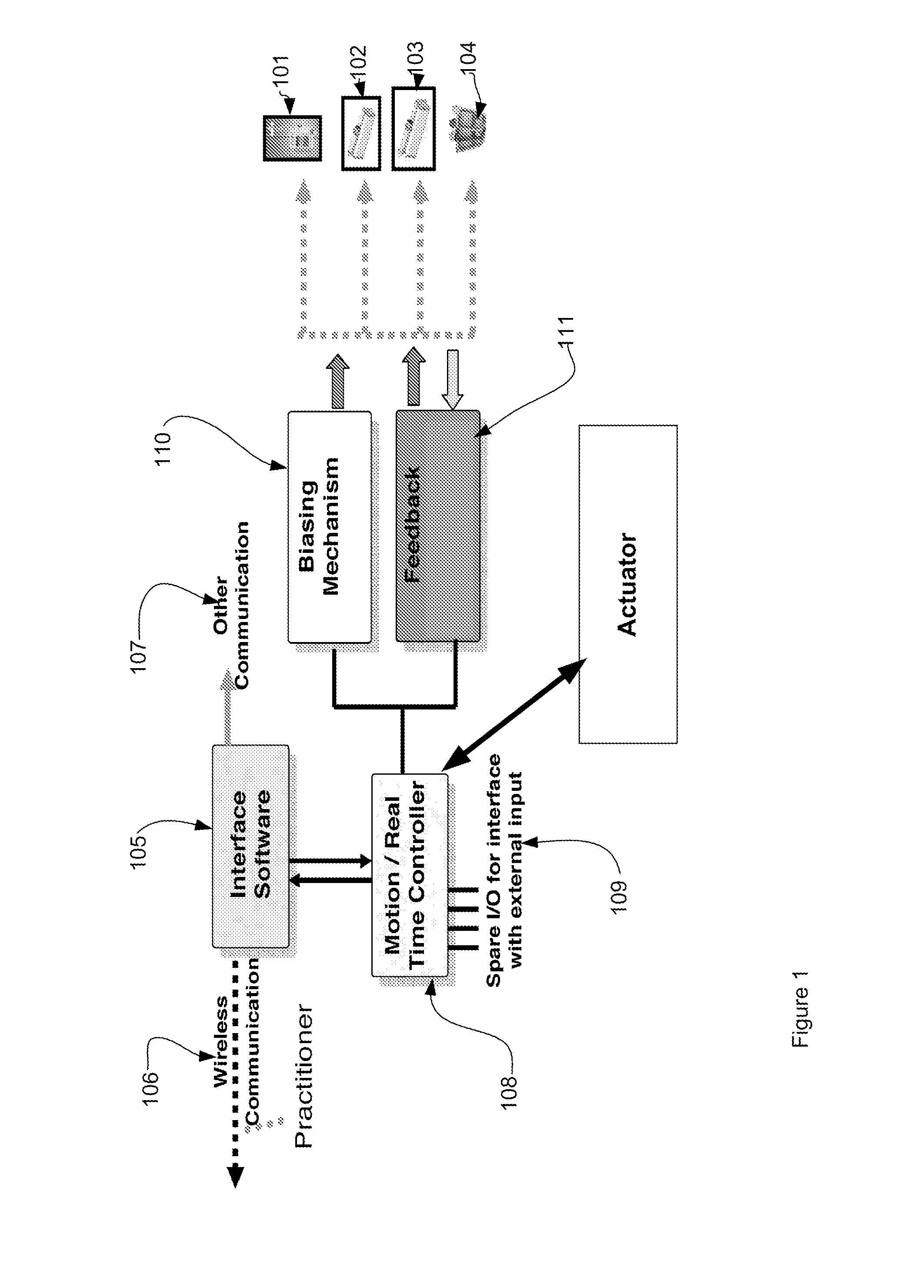
[0018]Other embodiments of the invention provide motor driven syringe pumps. In one embodiment linear motor driven pumps are provided. In another embodiment lead screw driven syringe pumps are provided. Combinations of position sensors for syringe plunger position, and optical, and other sensors, for flow, bubble and pressure are included into a closed loop control system for volume delivered and rate of delivery. In another embodiment the sensors further provide a fail safe system for malfunctions such as occlusions, leaks or disconnected tubing.

Problems solved by technology

Infusion pumps are used to administer fluids in ways that would be impractically expensive or unreliable if performed manually by nursing staff.
These delivery volumes levels are too small for a drip and the delivery rate and timing are not practical for manual injections.
Although the use of infusion pumps for very small volumes of often very potent drugs has begun, the accuracy of infusion pumps is still an issue.
A recent study of commercially available infusion pumps has found significant errors in delivery volumes.
Over-dosing or under-dosing can result in adverse short term responses to potent drugs and multiple requests for dosing.
This has resulted in limiting the use of infusion pumps to therapies where the detrimental effects of overdosing and under-dosing are limited.
Highly potent medications delivered in small volumes are not candidates for today's infusion pump technology.
However these type syringes vary and the force required to move the syringe piston, or plunger, a given distance to deliver a given volume may not be the same from one syringe to the next.
This variation in force without a suitable feedback control system will result in errors in delivered volume.
However these control methods are still missing from medical devices such as infusion pumps.

Method used


Image

  • High Precision Infusion Pumps
  • High Precision Infusion Pumps
  • High Precision Infusion Pumps

Examples


Embodiment Construction

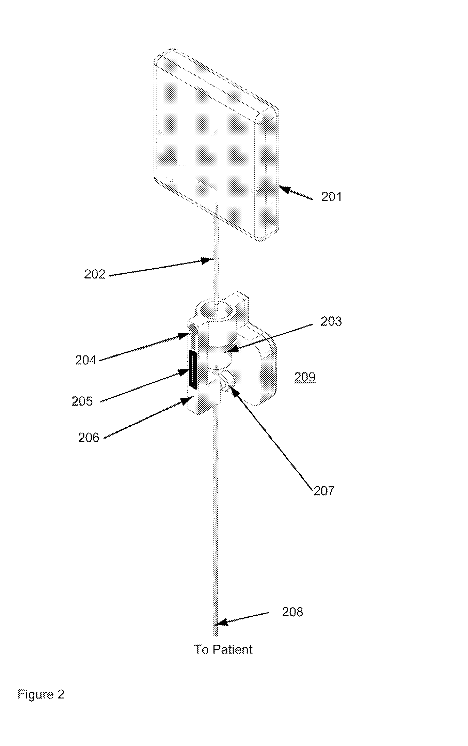
[0032]Control of the flow from an infusion system is a key feature of the invention. A system architecture embodiment provides an outline of a means for closed loop feedback control of infusion pump systems. The architecture is shown applicable to simple low cost gravity driven systems and to servo motor driven systems. Generally speaking the architecture is applicable to the precise control of all infusion pumps where flow is created using a biasing force (eg, motor, spring, gravity and the like) and where a means of feedback that is a measure of the actual flow rate is provided. Physical embodiments of several syringe systems are shown. The control architecture applies to all pump embodiments and is in fact scaleable to other medical devices as discussed below. The architecture is modular and scaleable. It consists of a real time controller that provides precise, accurate, closed loop control of the flow. The term “Biasing Mechanism” in the following discussions refers to all poss...


PUM


Abstract

A system architecture for closed loop control of infusion devices is described. The architecture provides means to control the flow from an infusion device as well as in some embodiments the pressure of the delivery. A variety of infusion systems are described that use the closed loop control architecture. In some embodiments the closed loop control may be adapted to current commonly used infusion means such as a gravity feed intravenous system. Other embodiments describe infusion pump system that use biasing or drive mechanisms of springs, elastomers, rotary and linear motors.

Description

CROSS-REFERENCE TO RELATED APPLICATIONS[0001]This application claims the benefit of: U.S. Provisional Patent Application 60 / 994,194, filed Sep. 17, 2007, entitled, “More Apparatuses for Low Cost Infusion Pumps, currently pending, by the same inventors, incorporated by reference, and, U.S. Provisional Patent Application 61 / 003,384, filed Nov. 15, 2007 entitled “Cost-Effective, High Precision Infusion Pumps” currently pending, by the same inventors and incorporated by reference.TECHNICAL FIELD[0002]This invention presents apparatuses for infusion pumps, infusion pump controllers, and describes the methods for their control.BACKGROUND[0003]An infusion pump infuses fluids, medication or nutrients into the circulatory system of the patient being treated. Infusion pumps are used to administer fluids in ways that would be impractically expensive or unreliable if performed manually by nursing staff. Commercial infusion pumps can administer injections as small as tens of nanoliters in a sing...

Claims


Application Information

Patent Timeline
IPC IPC(8): A61M5/168A61M5/145
CPCA61M5/141A61M2205/3389A61M5/1456A61M5/14586A61M5/16813A61M5/1684A61M5/16881A61M5/1689A61M5/172A61M2205/3317A61M2205/3592A61M2205/3306Y10S128/12Y10S128/13A61M5/1411A61M5/1454
Inventor SUNDAR, SATISHBALAKRISHNAN, SWAMINATHANMELNYK, IVAN
Owner VTITAN
Learn More