Dual walled combustors with impingement cooled igniters

a technology of impingement cooling and igniters, which is applied in the direction of machines/engines, burner ignition devices, lighting and heating apparatus, etc., can solve the problems of low cycle fatigue (lcf) failure of the igniter, and affecting the efficiency of the combustion process

Inactive Publication Date: 2010-08-26
HONEYWELL INT INC
View PDF7 Cites 90 Cited by
  • Summary
  • Abstract
  • Description
  • Claims
  • Application Information

AI Technical Summary

Problems solved by technology

However, over time, continued operation may induce potentially damaging thermal stresses into the combustor that exceed the strength of materials used in fabricating the components of the combustor.
For example, thermally induced transient and steady state stresses may cause low cycle fatigue (LCF) failure of the igniter.
Cooling the igniter, particularly the tip portion of the igniter closest to the combustion process, frequently presents challenges.
However, this arrangement is generally not very efficient because it typically requires a relatively large amount of cooling air to sufficiently cool the tip portion of the igniter.
The large amount of air used to effectively cool the tip portion of the igniter in this manner may adver

Method used


Image

  • Dual walled combustors with impingement cooled igniters
  • Dual walled combustors with impingement cooled igniters
  • Dual walled combustors with impingement cooled igniters

Examples


Embodiment Construction

[0018]The following detailed description of the invention is merely exemplary in nature and is not intended to limit the invention or the application and uses of the invention. Furthermore, there is no intention to be bound by any theory presented in the preceding background of the invention or the following detailed description of the invention.

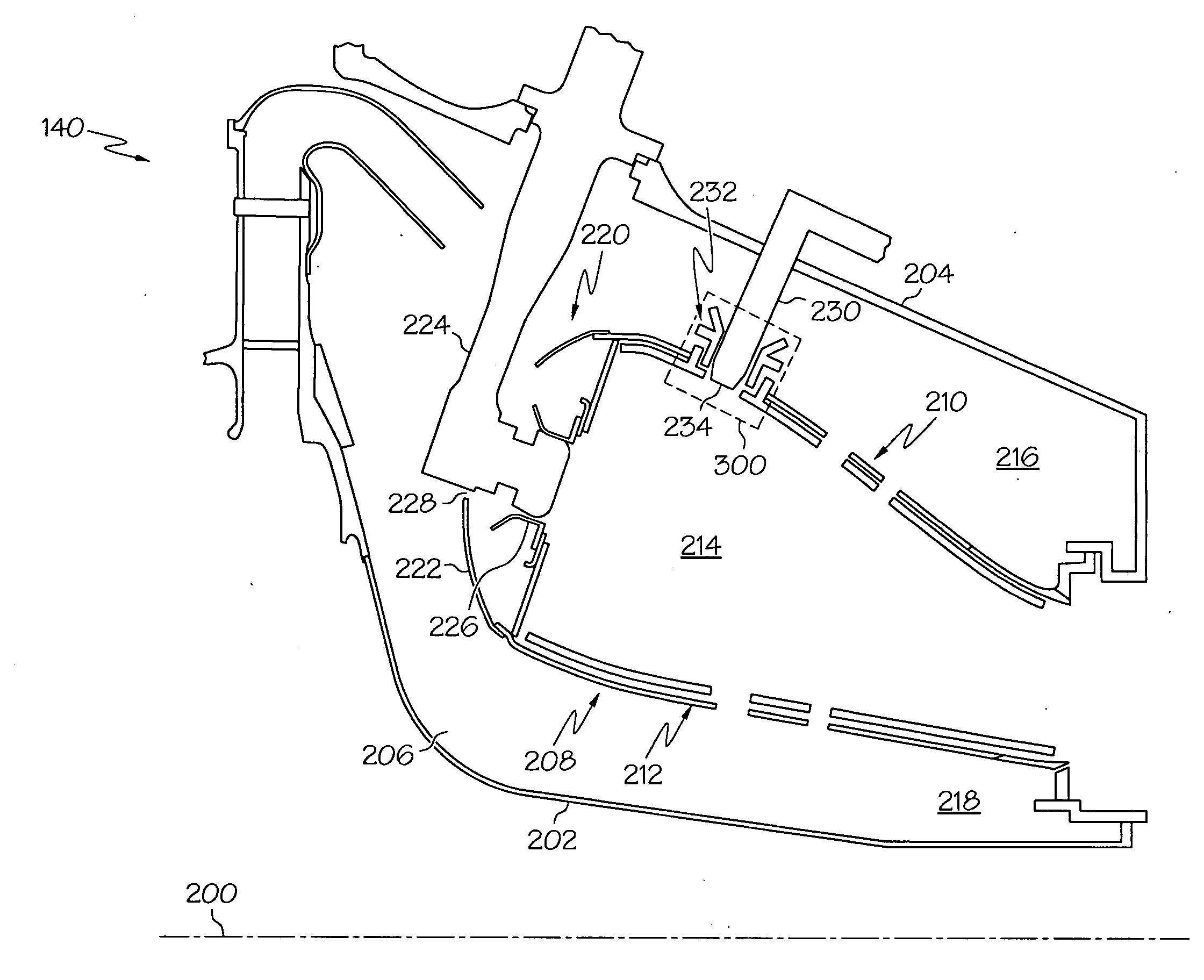
[0019]Broadly, exemplary embodiments discussed herein relate to dual walled combustors. More particularly, the dual walled combustor includes an igniter tube that mounts an igniter to an outer liner of a combustion chamber. The igniter tube has a number of holes that direct cooling impingement air onto a tip portion of the igniter. For example, the igniter tube may include a hot boss mounted on the inner wall of the liner with a first set of holes and a cold boss mounted on the outer wall of the liner with a second set of holes. The hot and cold bosses may be arranged such that cooling air enters the second set of holes, flows through a cavi...


PUM


Abstract

A combustor for a gas turbine engine includes an inner liner and an outer liner circumscribing the inner liner and forming a combustion chamber with the inner liner. The outer liner is a dual walled liner with a first wall and a second wall. The combustor includes a fuel igniter comprising a tip portion configured to ignite an air and fuel mixture in the combustion chamber and an igniter tube positioning the fuel igniter relative to the combustion chamber. The igniter tube includes a plurality of holes configured to direct cooling air toward the tip portion of the fuel igniter.

Description

FIELD OF THE INVENTION[0001]The following description generally relates to combustors for gas turbine engines, and more particularly relates to combustors with impingement cooled igniters and igniter tubes for improved cooling of igniters.BACKGROUND[0002]A gas turbine engine may be used to power various types of vehicles and systems. A particular type of gas turbine engine that may be used to power aircraft is a turbofan gas turbine engine. A turbofan gas turbine engine conventionally includes, for example, five major sections: a fan section, a compressor section, a combustor section, a turbine section, and an exhaust section. The fan section is typically positioned at the front, or “inlet” section of the engine, and includes a fan that induces air from the surrounding environment into the engine and accelerates a fraction of this air toward the compressor section. The remaining fraction of air induced into the fan section is accelerated into and through a bypass plenum and out the ...

Claims


Application Information

Patent Timeline
IPC IPC(8): F02C7/22F02C7/264
CPCF02C7/264F23D2207/00F23R3/002F05D2260/201F23R2900/03042F23R2900/03044Y02T50/675F23R3/06F23R3/60F23R2900/00012Y02T50/60
Inventor BRONSON, THOMAS J.RUDRAPATNA, NAGARAJAKETTINGER, JONZUPANC, FRANK JOSEPH
Owner HONEYWELL INT INC
Why Eureka
Try Eureka