Pneumatic tire

a technology of pneumatic tires and zigzag grooves, applied in the field of pneumatic tires, can solve the problems of reducing the performance of dry grip, low rigidity, and large slippage of these portions with the road, and achieve the effects of preventing the generation of uneven wear as a result of external portions of zigzag grooves, enhancing on-snow performance, and preventing uneven wear

Active Publication Date: 2010-08-26
SUMITOMO RUBBER IND LTD
View PDF4 Cites 22 Cited by
  • Summary
  • Abstract
  • Description
  • Claims
  • Application Information

AI Technical Summary

Benefits of technology

[0013]As stated above, in the present invention, a straight groove that ridge lines at which groove wall surfaces intersect with the tread surface extend straight in the circumferential direction, is used as a circumferential main groove to be disposed in the outer region. Therefore, generation of uneven wear as resulting from external portions of a zigzag groove can be prevented. Moreover, the groove wall surface is formed of a gently-inclined upper wall portion and a steeply-inclined lower wall portion. Since the upper wall surface portion is gently-inclined, it functions as a chamfered portion that a corner portion of the groove wall surface and the tread surface is

Problems solved by technology

However, as shown in FIG. 11(A), external corner portions “g1a” projecting toward a groove width center side in zigzag grooves “g1” are low in rigidity and, therefore, amount of slip of these portions with a road is large.
Therefore, there is a problem that such an uneven wear that the external corner portions “gla” are worn away early generates to result in lowering of dry grip performance.
In particular, since a large load is applied during cornering to an outer region of a tread surface which is located on an outer side of a vehicle, circumferential main grooves disposed in the outer region cause uneven wear more

Method used


Image

  • Pneumatic tire
  • Pneumatic tire
  • Pneumatic tire

Examples


examples

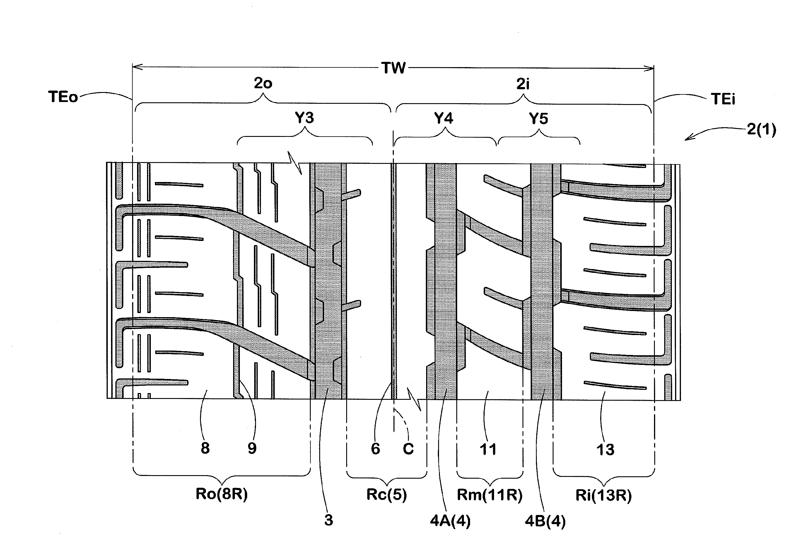
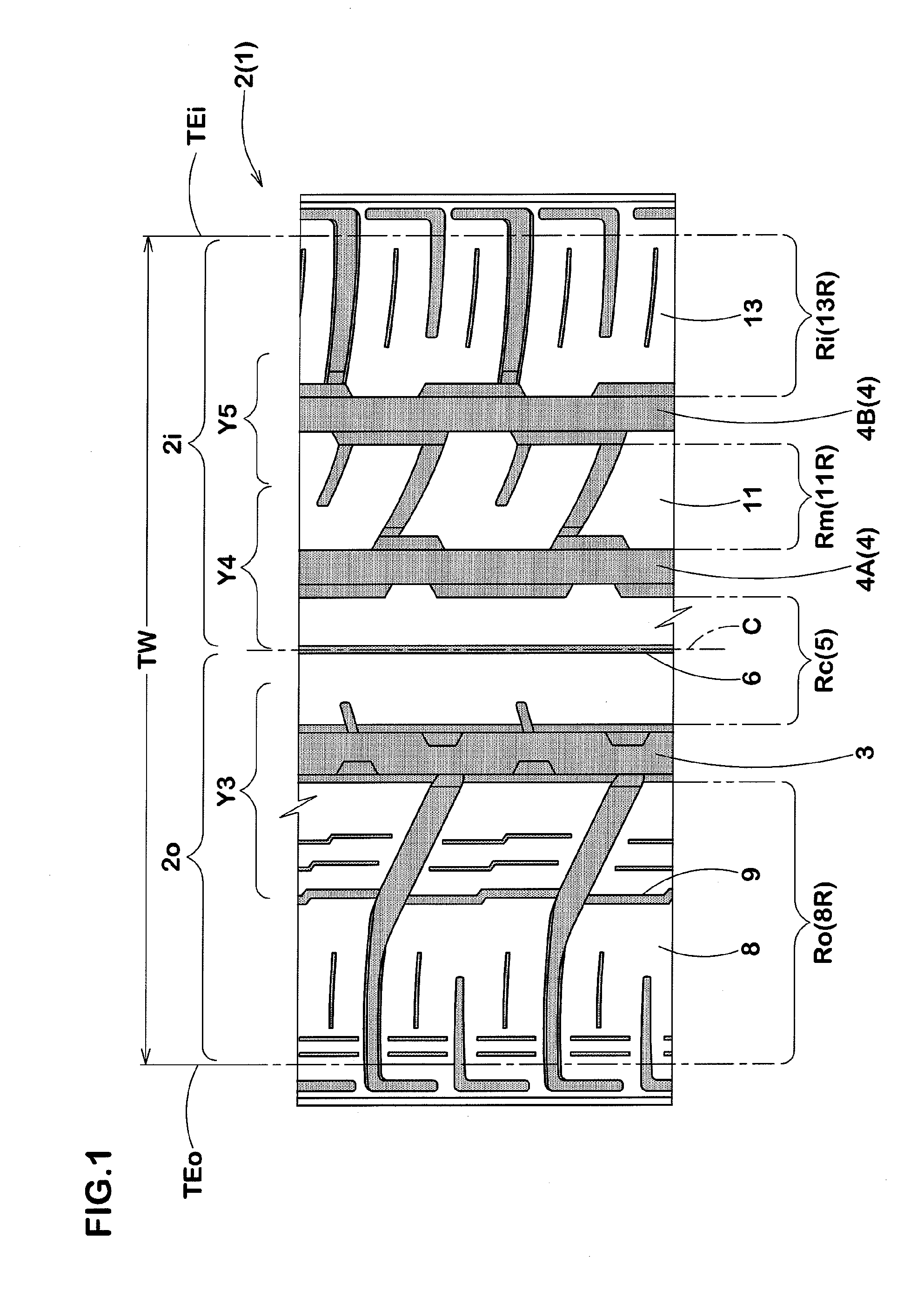
[0082]In order to confirm the effects of the present invention, radial tires for passenger cars (inner structure being common to all tires) having a size of 255 / 40R20 and a basic pattern shown in FIG. 1 were manufactured based on the specifications shown in Table 1, and were tested with respect to cornering performance (on dry road), uneven wear resistance and on-snow performance. Comparative Example 1 and Example 1 are the same except the outer region circumferential main groove 3. Example 1 and Example 2 are the same except the inner region circumferential main grooves 4A and 4B.

[0083]The tires were mounted on rims (20×9.0JJ) and attached to four wheels of a passenger car (Japanese 3,500 cc 4WD vehicle) under an inner pressure of 230 kPa. The test car was run on a tire test course of a snow-covered road, and steering stability including braking performance was evaluated by a driver's feeling. The results are shown by an index based on a result of Example 1 regarded as 100. The lag...


PUM


Abstract

A pneumatic tire having on-snow performance improved by increasing traction performance on snow-covered road with maintaining dry grip performance high, and comprising tread surface 2 having at least one circumferential main groove 3 in an outer region 2o facing outward of a vehicle, the circumferential main groove 3 being a straight groove wherein ridge lines 21 at which groove wall surfaces 20 intersect with the tread surface 2 extend straight, each groove wall surface 20 comprising a gently-inclined upper wall surface 20U extending from the ridge line 21 at an angle θ1 of 40 to 60° with respect to a normal line to tread surface 2 and a steeply-inclined lower wall surface 20L extending to groove bottom 22 at an angle θ2 smaller than the angle θ1, and the lower wall surface 20L including projections 23 which are disposed at intervals in the circumferential direction and have a triangular cross section with slope surface 23S extending from lower end Ue of the upper wall surface 20U to groove bottom 22 at an angle θ3 which is not greater than the angle θ1 but is greater than the angle θ2.

Description

TECHNICAL FIELD[0001]The present invention relates to a pneumatic tire suitable for use as an all season tire and having an on-snow performance improved with maintaining a running performance on dry roads at a high level.BACKGROUND ART[0002]For all season tires having a good running performance on snow-covered roads (i.e., on-snow performance) improved with maintaining a high speed running performance, it is important to enhance a traction performance on snow-covered roads. For this purpose, zigzag grooves have been generally used as circumferential main grooves extending in a circumferential direction of tire. However, as shown in FIG. 11(A), external corner portions “g1a” projecting toward a groove width center side in zigzag grooves “g1” are low in rigidity and, therefore, amount of slip of these portions with a road is large. Therefore, there is a problem that such an uneven wear that the external corner portions “gla” are worn away early generates to result in lowering of dry g...

Claims


Application Information

Patent Timeline
IPC IPC(8): B60C11/117
CPCB60C11/0304B60C11/0306B60C11/0309B60C11/1369B60C2011/0381B60C11/1323B60C11/033B60C2011/0383B60C11/1392
Inventor MURATA, TAKEHIKO
Owner SUMITOMO RUBBER IND LTD
Why Eureka
Try Eureka