Positive-pressure flying aircraft

a technology of positive pressure and flying aircraft, applied in the field of aircraft, can solve the problems of aircraft stalling, not being stabilized, and difficult for aircraft to run on the ground

Active Publication Date: 2010-08-26
BELLSION
View PDF11 Cites 3 Cited by
  • Summary
  • Abstract
  • Description
  • Claims
  • Application Information

AI Technical Summary

Benefits of technology

[0006]It is an object of the invention to provide a positive-pressure flying aircraft in which relative air stream pushes an aircraft body for flying, the aircraft stably flying with a large angle of attack at low speed and in landing or takeoff.

Problems solved by technology

As an angle of attack of the wing increases, air stream is likely to leave the leading edge of the wing, so that the aircraft goes into a stall or is not stabilized to crash.
Thus, it is very difficult for the aircraft to run on the ground while such a large angle of the attack is kept.

Method used


Image

  • Positive-pressure flying aircraft
  • Positive-pressure flying aircraft
  • Positive-pressure flying aircraft

Examples


embodiment 1

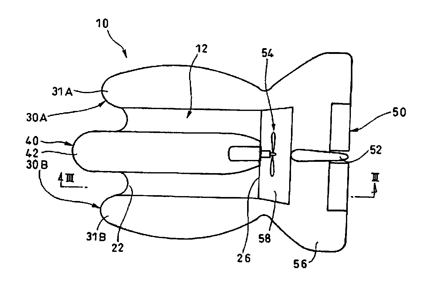
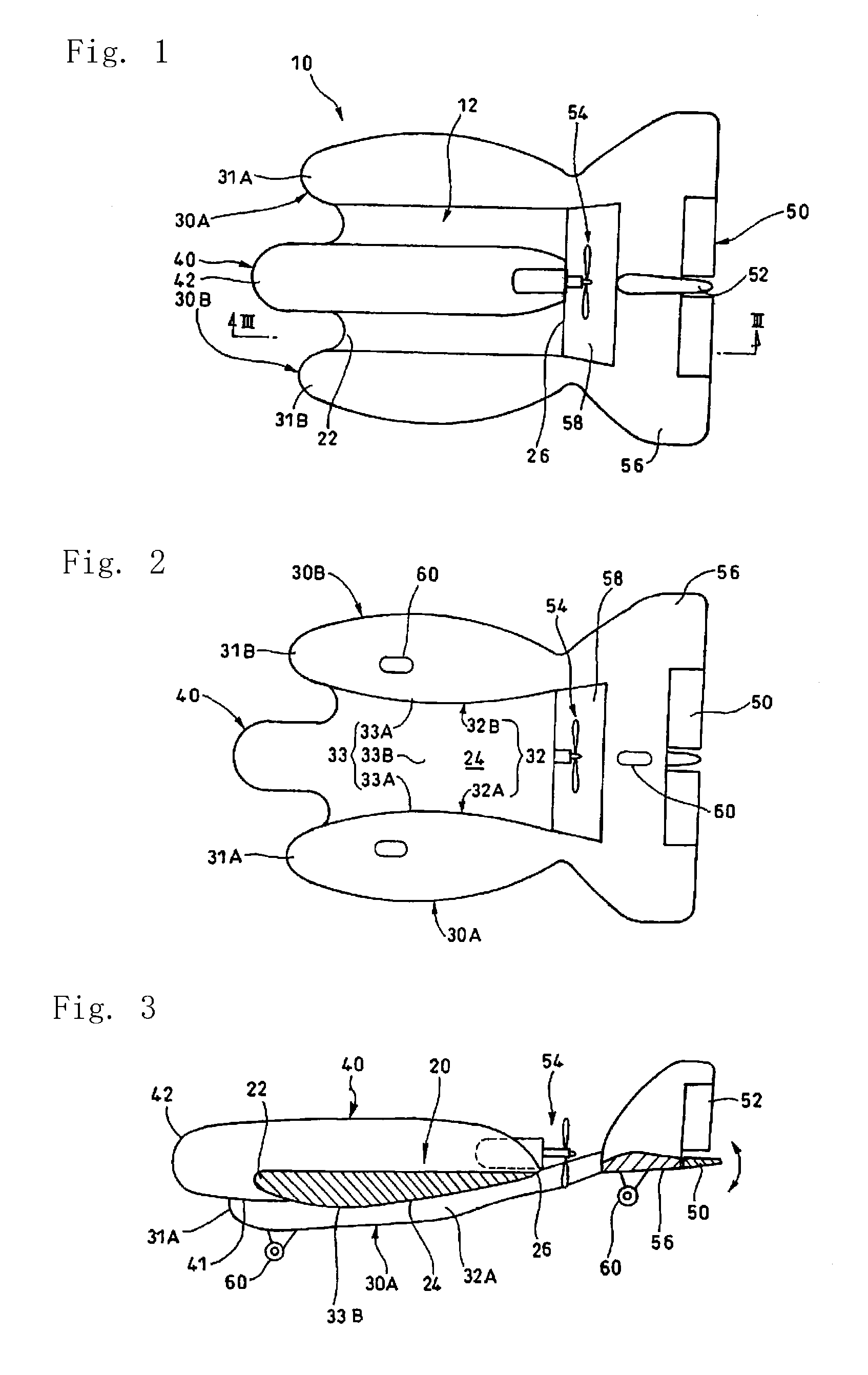
[0042]In FIGS. 1 and 2, a positive-pressure-flying aircraft 10 in Embodiment 1 comprises a wing 12; a right-side body 30A; a left-side body 30B, a middle body 40; an elevator 50; a rudder 52; a propeller 54 at the rear end of the middle body 40; and a horizontal stabilizer 56 that extends horizontally.

[0043]An elevator 50 is mounted to the rear end of the horizontal stabilizer 56. In FIG. 3, the wing 12 has a rounded leading edge 22 and an acute trailing edge 26. The maximum thickness portion 21 is located at 2 / 10 to 3 / 10 of the chord length.

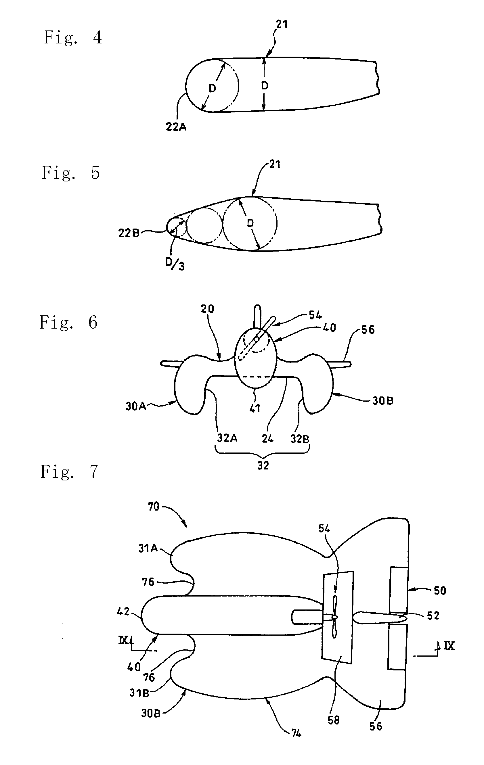
[0044]The thickness of the maximum thickness portion 21 of the wing 12 is 3 / 10 to 4 / 10, preferably 35 / 100, of the cord length.

[0045]The diameter of an arc of the leading edge 22 is defined as ⅓ of the thickness of the maximum thickness portion 21. For example, the leading edge 22A has a diameter that is equal to the maximum thickness D in FIG. 4, or D / 3. In FIG. 5, between a circle of the diameter D and a circle of the diameter D / 3, a circle of ...

embodiment 2

[0074]A positive-pressure flying aircraft 70 in Embodiment 2 of the present invention will be described in FIGS. 7 to 10.

[0075]The positive-pressure flying aircraft 70 is a whole-wing-type aircraft which has a wing 74 equal to the right and left bodies in Embodiment 1 in height. In an air trap 72, the sum of widths of right and left side walls 73 forming right and left guide surfaces 73A,73B is equal to the width of the wing 74. The air trap 72 is defined by the right and left guide surfaces 73A, 73B and a bottom surface 72A.

[0076]In the middle of the wing 74, a middle body 40 similar to that of Embodiment 1 is provided. The front end of the middle body 40 is positioned in front of the front end of the wing 74, and concaves 76 are formed in FIGS. 7 and 8. With the concaves 76, hemispherical leading edges 31A,31B having vertical cross sections identical with those of the right and left bodies 30A,30B in Embodiment 1 are formed.

[0077]With respect to other structure, the same numerals ...


PUM


Abstract

Provided is a positive-pressure floating type airplane comprising an airfoil portion, left-right fuselages, a central fuselage, an elevator and a rudder disposed at the back of the airfoil portion, a thruster disposed at the back of the central fuselage, and a horizontal stabilizer disposed at the rear ends of the left-right fuselages. The individual front ends of the airfoil portion, the left-right fuselages and the central fuselage are formed into arcuate shapes in longitudinal sections. On the lower side of the airfoil portion, a recessed air capture is formed from the front end to the rear end. As a result, the positive-pressure floating type airplane is floated by the reaction from the air at the time when the air to pass the air capture through the airfoil portion is pushed by the thrust of the thruster, and is propelled forward by the component of that thrust.

Description

TECHNICAL FIELD[0001]The present invention relates to an aircraft, and particularly to a positive-pressure flying aircraft that flies by relative air stream or positive pressure to an aircraft body.BACKGROUND OF THE INVENTION[0002]In an aircraft, owing to difference in velocity of air stream flowing on the upper and lower surfaces of a wing, negative pressure generated on the upper surface raises the aircraft body. As an angle of attack of the wing increases, air stream is likely to leave the leading edge of the wing, so that the aircraft goes into a stall or is not stabilized to crash.[0003]JP2004-106784A discloses a kite-type aircraft pushed by air stream or positive pressure to fly.[0004]In the kite-type aircraft, the angle of attack of the aircraft body is nearly 60 degrees at low speed or in landing which is similar to a kite. However, a jetting device jets out a gas obliquely downward along the wing on the upper surface of the aircraft body to generate propelling force or lift...

Claims


Application Information

Patent Timeline
Patent Type & Authority Applications(United States)
IPC IPC(8): B64C39/04
CPCB60V1/08B64B2201/00B64C39/04
Inventor SUZUKI, MASAHIKO
Owner BELLSION
Why Eureka
Try Eureka