Antenna Apparatus

a technology of antenna and antenna core, which is applied in the structure of loop antenna with ferromagnetic core, instruments, radiating elements, etc., can solve the problems of inability to achieve power, inability to communicate with the reader/writer, etc., and achieve the effect of expanding the communication range and increasing the communication distan

Inactive Publication Date: 2010-08-26
DEXERIALS CORP +1
View PDF3 Cites 19 Cited by
  • Summary
  • Abstract
  • Description
  • Claims
  • Application Information

AI Technical Summary

Benefits of technology

[0011]According to the embodiment of the present invention, the antenna apparatus can be small and thin. It can yet increase the communication distance with respect to the electronic apparatus having a communication function, thereby expanding the communication range.

Problems solved by technology

However, the IC card may fail to communicate with the reader / writer if it incorporates an IC tag having communication frequency of 13.56 MHz.
As a result, no power can be attained.

Method used


Image

  • Antenna Apparatus
  • Antenna Apparatus
  • Antenna Apparatus

Examples


Embodiment Construction

[0020]Antenna apparatuses according to an embodiment of the present invention will be described with reference to the drawings appended hereto.

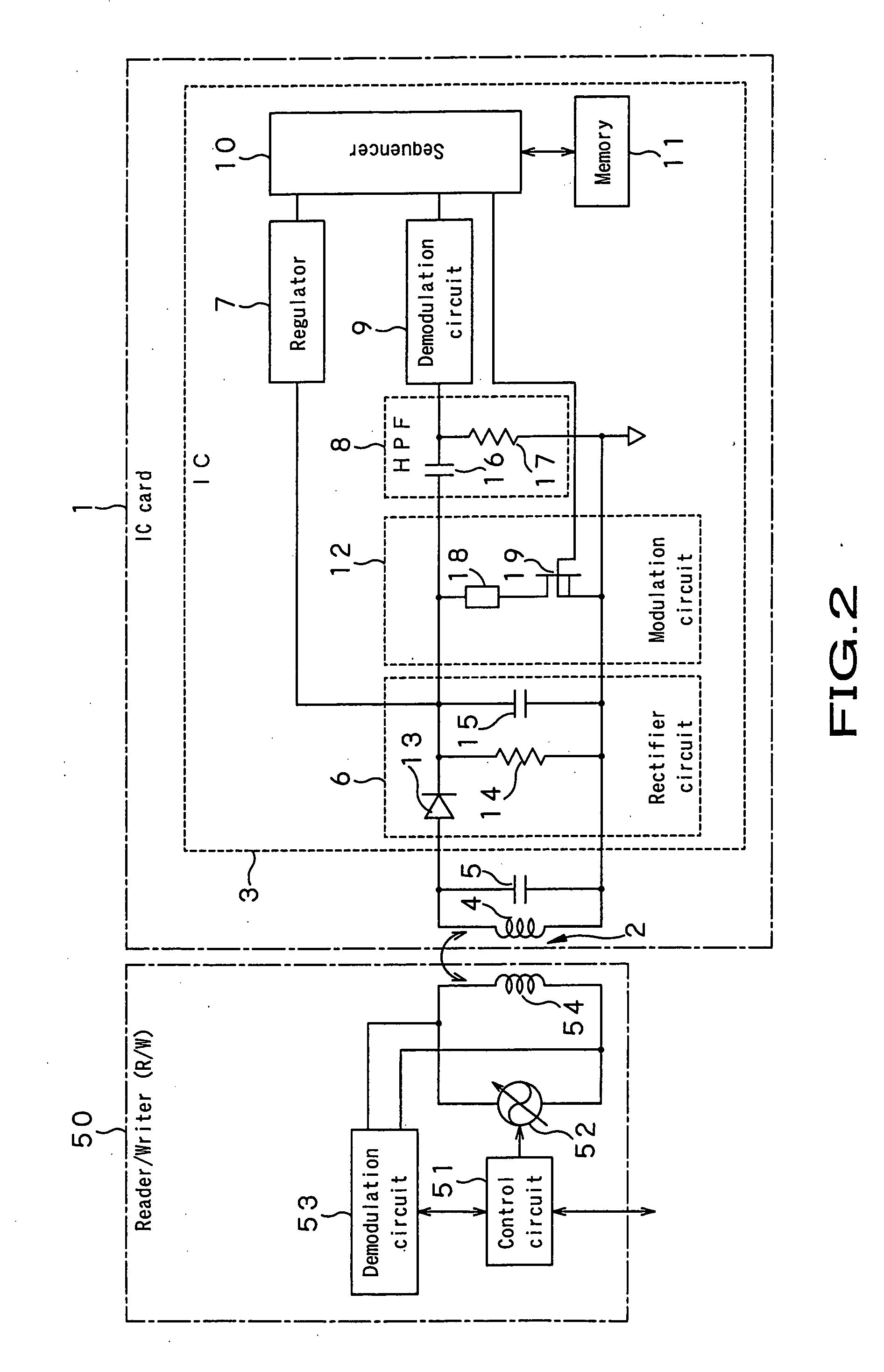
[0021]First, an RFID system using an antenna apparatus according to the embodiment will be explained. As shown in FIG. 2, the RFID system includes a non-contact type IC card 1 and a reader / writer 50 (hereinafter referred to as R / W). The R / W 50 can write data into, and read data from, the IC card 1.

[0022]The IC card 1 is a battery-less IC card that does not incorporate a power supply such as a battery, in compliance with, for example, ISO7810 Standard. The IC card 1 is of the same size as a so-called credit card. That is, it is rectangular and has such short sides and long sides that it can be placed, in its entirety, on the palm of the hand. The IC card 1 incorporates a substrate and has a loop antenna 2 and an integrated circuit (IC) 3. The loop antenna 2 and the IC 3 are mounted on the substrate. The loop antenna 2 receives and transmits da...


PUM


Abstract

The present invention provides an antenna apparatus (60) for use in a non-contact type IC card into and from which data can be written and read by an electronic apparatus having a communication function, by virtue of inductive coupling. The antenna apparatus includes a loop coil (61) and a magnetic member (62). The loop coil (61) is produced by winding a conductive wire in a plane and configured to perform the inductive coupling with the electronic apparatus. The magnetic member (62) covers one region (61a) of the loop coil, provided at one side, from one surface of the loop coil, passes through the loop coil, and covers the other region (61b) of the loop coil, provided at the other side, from the other surface of the loop coil.

Description

TECHNICAL FIELD[0001]The present invention relates to an antenna apparatus for use in non-contact type IC cards into and from which data can be written and read when the cards are induction coupled with an electromagnetic field by electronic apparatuses having a communication function.[0002]This application is based upon and claims the benefit of priority from the prior Japanese Patent Application No. 2005-174178, filed in Japan on Jun. 14, 2005, the entire content of which is incorporated herein by reference.RELATED ART[0003]In recent years, so-called radio frequency identification (RFID) systems that use non-contact type IC cards or IC tags have been introduced into automatic ticket gates at railway stations, entrance / exit security systems, electronic money systems, and the like. As FIG. 1 schematically shows, the RFID system includes a non-contact type IC card 100 and a reader / writer 101. The reader / writer 101 can write data into, and read data from, the IC card 100. In the RF sy...

Claims


Application Information

Patent Timeline
Patent Type & Authority Applications(United States)
IPC IPC(8): H01Q7/00
CPCG06K19/07749G06K19/07779H01Q7/06H01Q1/2225G06K19/07783H01Q7/00G06K19/07G06K19/077H01Q1/36
Inventor SUGITA, SATORUARAMAKI, KEISUKEAKIHO, HIRAKU
Owner DEXERIALS CORP
Why Eureka
Try Eureka