
Liquid ejecting head unit and liquid ejecting apparatus

a liquid ejecting head and liquid ejecting technology, which is applied in printing, inking apparatus, other printing apparatus, etc., can solve the problems of lowering the accuracy of liquid droplet target positions, difficulty in positioning liquid ejecting heads with high accuracy, and chipping of keys and key grooves on the member formed of silicon substrates, etc., to achieve the effect of high accuracy

Active Publication Date: 2010-08-26
SEIKO EPSON CORP
View PDF4 Cites 16 Cited by
  • Summary
  • Abstract
  • Description
  • Claims
  • Application Information

AI Technical Summary

Benefits of technology

[0012]An advantage of some aspects of the invention is to provide a liquid ejecting head unit and a liquid ejecting apparatus, which are capable of satisfactorily maintaining the positioning accuracy thereof even if the liquid ejecting heads are repeatedly attached and detached to and from the base plate.
[0014]According to the aspect of the invention, each of the positioning pins is fixed to the base plate in a state being positioned with high accuracy. Therefore, each of the heads may be positioned to the base plate extremely easily and highly accurately. Moreover, the positioning accuracy may be satisfactorily maintained even if the liquid ejecting heads are repeatedly attached and detached to and from the base plate.
[0018]According to another aspect of the invention, a liquid ejecting apparatus includes the liquid ejecting head unit as described above. The aspect of the invention provides a liquid ejecting apparatus, which is capable of positioning the liquid ejecting heads simply and with high accuracy.

Problems solved by technology

However, even if the liquid ejecting heads are positioned to a member such as the silicon substrate capable of positioning with high accuracy using the keys and the key groove as in Japanese Patent No. 2549762, it may be difficult to position the liquid ejecting heads with high accuracy.
If the attachment and detachment of the liquid ejecting heads to and from the base plate are repeated as described above, then there arises a risk that, for example, such a problem may occur that the keys and the key groove provided on the member formed of the silicon substrate become chipped.
Therefore, it should be understood that positional accuracy of the liquid ejecting heads to the base plate may be lowered, resulting in lowering of accuracy in target positions of liquid droplets.
Such a problem exists not only in the member formed of the silicon substrate but also commonly in general positioning members.
For example, there is apprehension that positioning portions of the base plate may be worn in that the attachment and detachment of the liquid ejecting heads to and from the base plate are repeated, resulting in lowering of the positional accuracy.
Note that such a problem exists not only in the ink jet recording head unit but also, in a similar way, in a liquid ejecting head unit that ejects a liquid other than ink.

Method used


Image

  • Liquid ejecting head unit and liquid ejecting apparatus
  • Liquid ejecting head unit and liquid ejecting apparatus
  • Liquid ejecting head unit and liquid ejecting apparatus

Examples


first embodiment

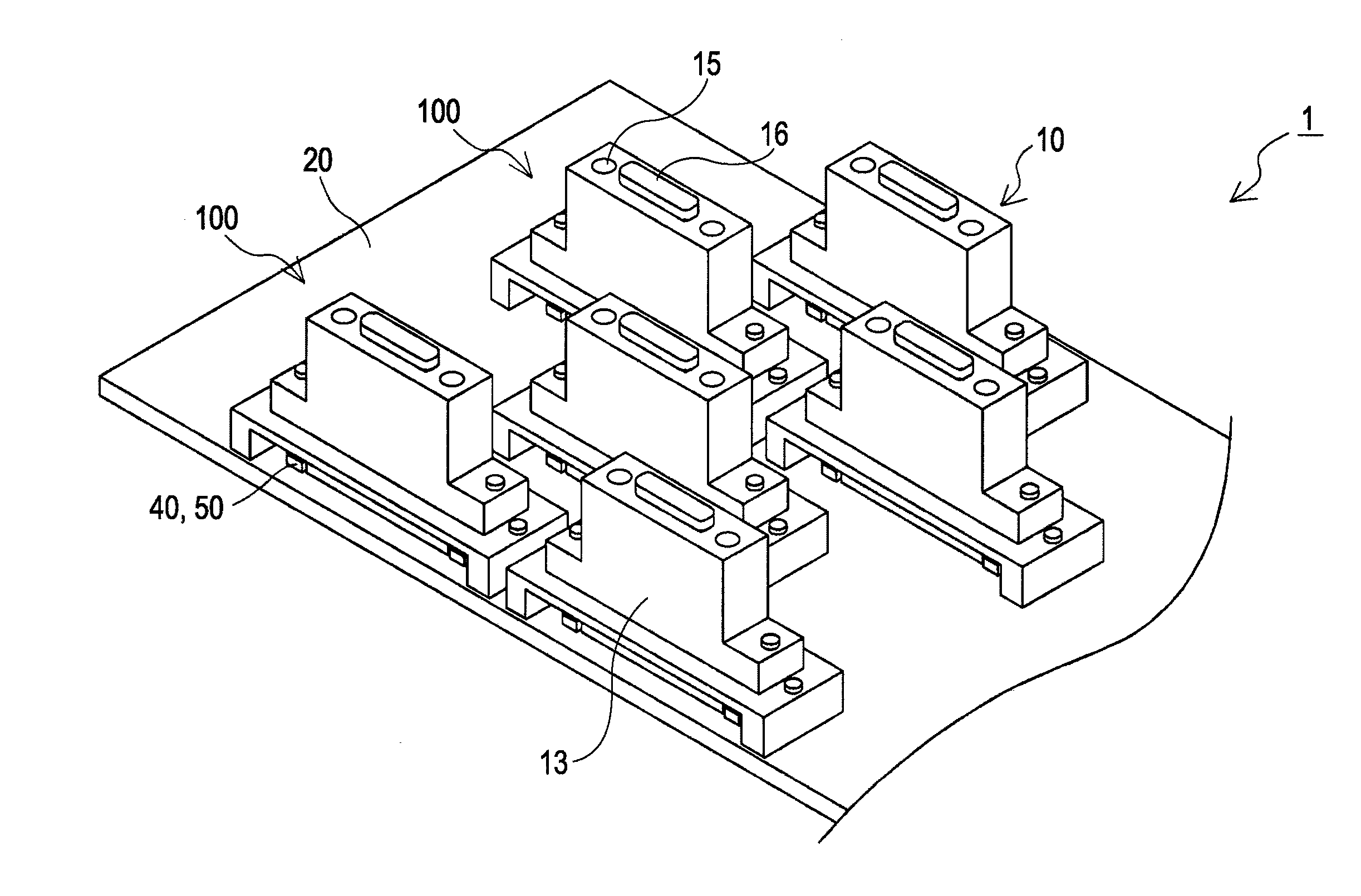
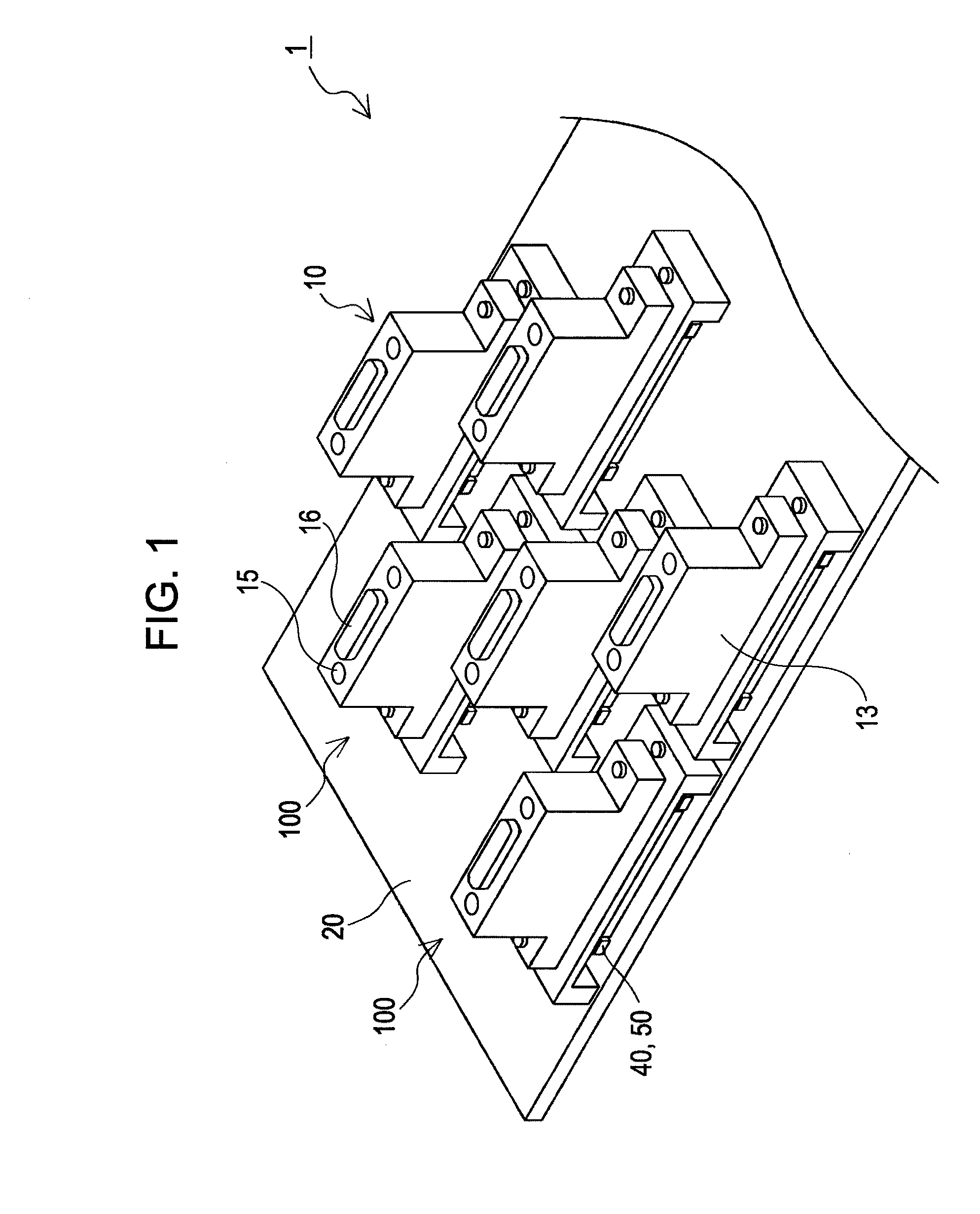
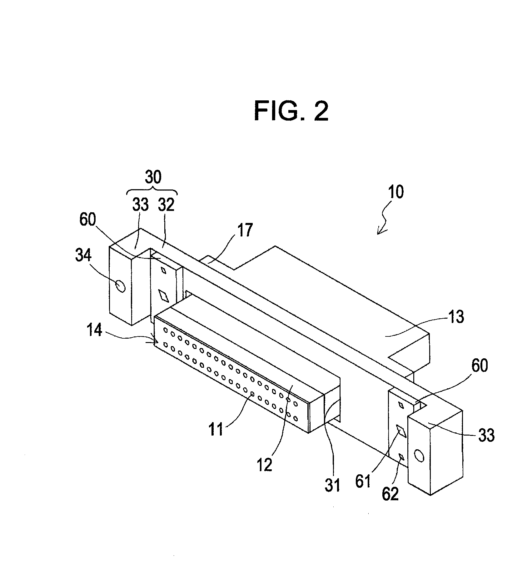
[0026]As shown in FIGS. 1 to 4, an ink jet recording head unit 1 (hereinafter referred to as a “head unit”) of this embodiment includes: a plurality of ink jet recording heads 10 (hereinafter referred to as “heads”); and a base plate 20 to which the plurality of heads 10 are fixed in a state being positioned at predetermined positions thereof.

[0027]For example, in the embodiment, the plurality (for example, three) of heads 10 are arranged along nozzle arrays 14 in which nozzles 11 are arrayed, whereby a head group 100 is configured, and on the base plate 20, two head groups 100 are provided in parallel to each other in the direction perpendicular to the nozzle arrays 14. The plurality of heads 10 which configure the respective head groups 100 are arranged in a zigzag fashion, and all of the nozzles 11 of the plurality of heads 10 are arranged at a predetermined pitch in the direction along the nozzle arrays 14.

[0028]In the base plate 20, through-holes 21 which penetrate the base pla...


PUM


Abstract

A liquid ejecting head unit includes: a plurality of liquid ejecting heads, each of which has a nozzle array in which nozzles ejecting liquid droplets are arrayed; a base plate to which the plurality of liquid ejecting heads are fixed in a state being positioned at predetermined positions thereof; and positioning pins which are fixed to the base plate and engaged with positioning holes formed in the liquid ejecting heads. Each of the positioning pins is held in a holding hole provided in a fixing plate fixed to the base plate. A reference plate is joined to a surface of each of the fixing plates. Further, in each of the reference plates, there are provided: an insertion hole in which the positioning pin is substantially inscribed; and a minute hole that serves as a reference for positioning the positioning pin to the base plate.

Description

BACKGROUND[0001]1. Technical Field[0002]The present invention relates to a liquid ejecting head unit and a liquid ejecting apparatus, which eject liquid droplets, and in particular, relates to an ink jet recording head and an ink jet recording apparatus, which eject ink droplets as the liquid droplets.[0003]2. Related Art[0004]A liquid ejecting apparatus represented by an ink jet recording apparatus such as an ink jet printer and an ink jet plotter includes a liquid ejecting head unit in which a plurality of liquid ejecting heads are provided. The liquid ejecting heads are capable of ejecting, from nozzles, a liquid such as ink reserved in a cartridge, a tank or the like.[0005]The plurality of liquid ejecting heads which configure the liquid ejecting head unit as described above are fixed at predetermined positions of a base plate as a holding member common thereto in a state being positioned with high accuracy. Specifically, the respective liquid ejecting heads are fixed to the bas...

Claims


Application Information

Patent Timeline
IPC IPC(8): B41J2/015
CPCB41J2/155B41J2202/20B41J2202/19
Inventor OGUCHI, SATOSHI
Owner SEIKO EPSON CORP
Learn More