Double standing valve sucker rod pump

a sucker rod pump and double-standing technology, applied in the direction of piston pumps, positive-displacement liquid engines, borehole/well accessories, etc., can solve the problems of gas lock, clogging of sucker rods with particulates, and several shortcomings of pumps

Active Publication Date: 2010-08-26
THOMPSON PUMP
View PDF13 Cites 13 Cited by
  • Summary
  • Abstract
  • Description
  • Claims
  • Application Information

AI Technical Summary

Benefits of technology

[0016]A movable piston of the pump is attached at the bottom of the rod string and reciprocates up and down in the pump housing in conjunction with the up and down movement of the rod string. The piston consists of a piston rod that attaches to the rod string on its upper end and is provided with an enlarged piston cap on its lower end. The piston cap is larger in diameter than the barrel and is held within the housing by the barre

Problems solved by technology

These prior art pumps suffer from several shortcomings, including

Method used


Image

  • Double standing valve sucker rod pump
  • Double standing valve sucker rod pump
  • Double standing valve sucker rod pump

Examples


Embodiment Construction

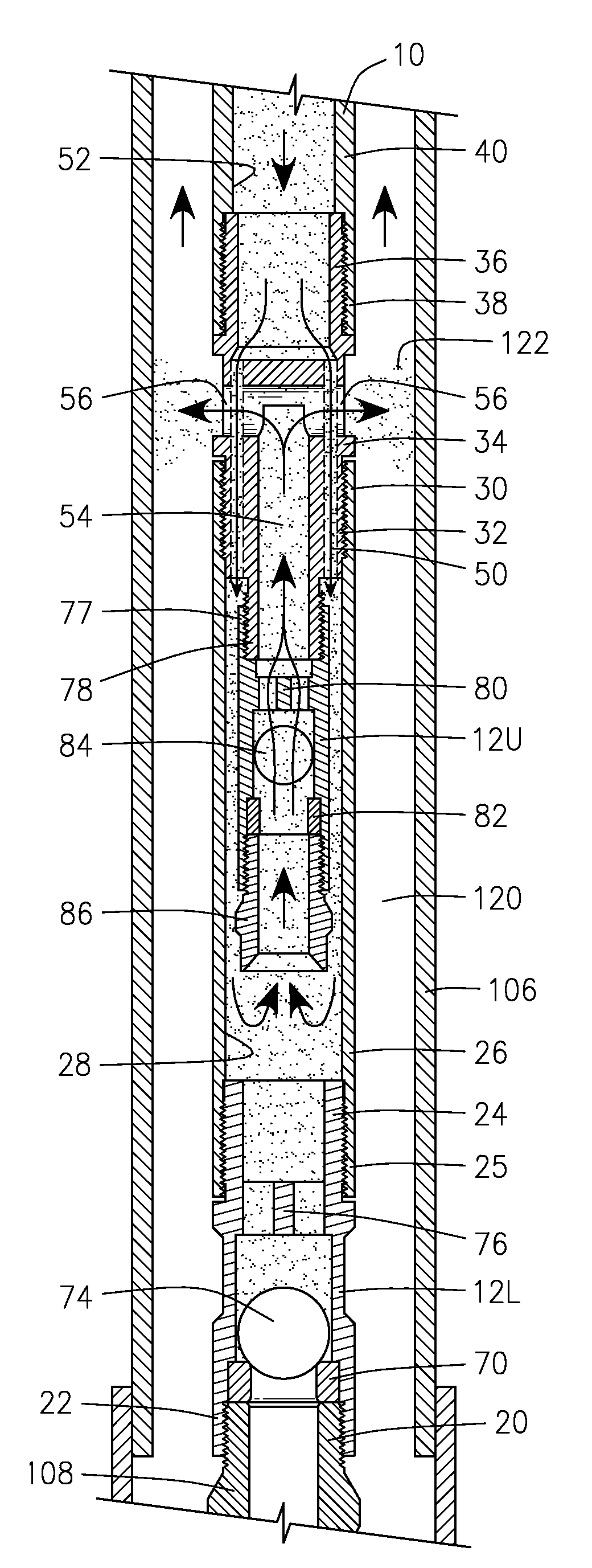
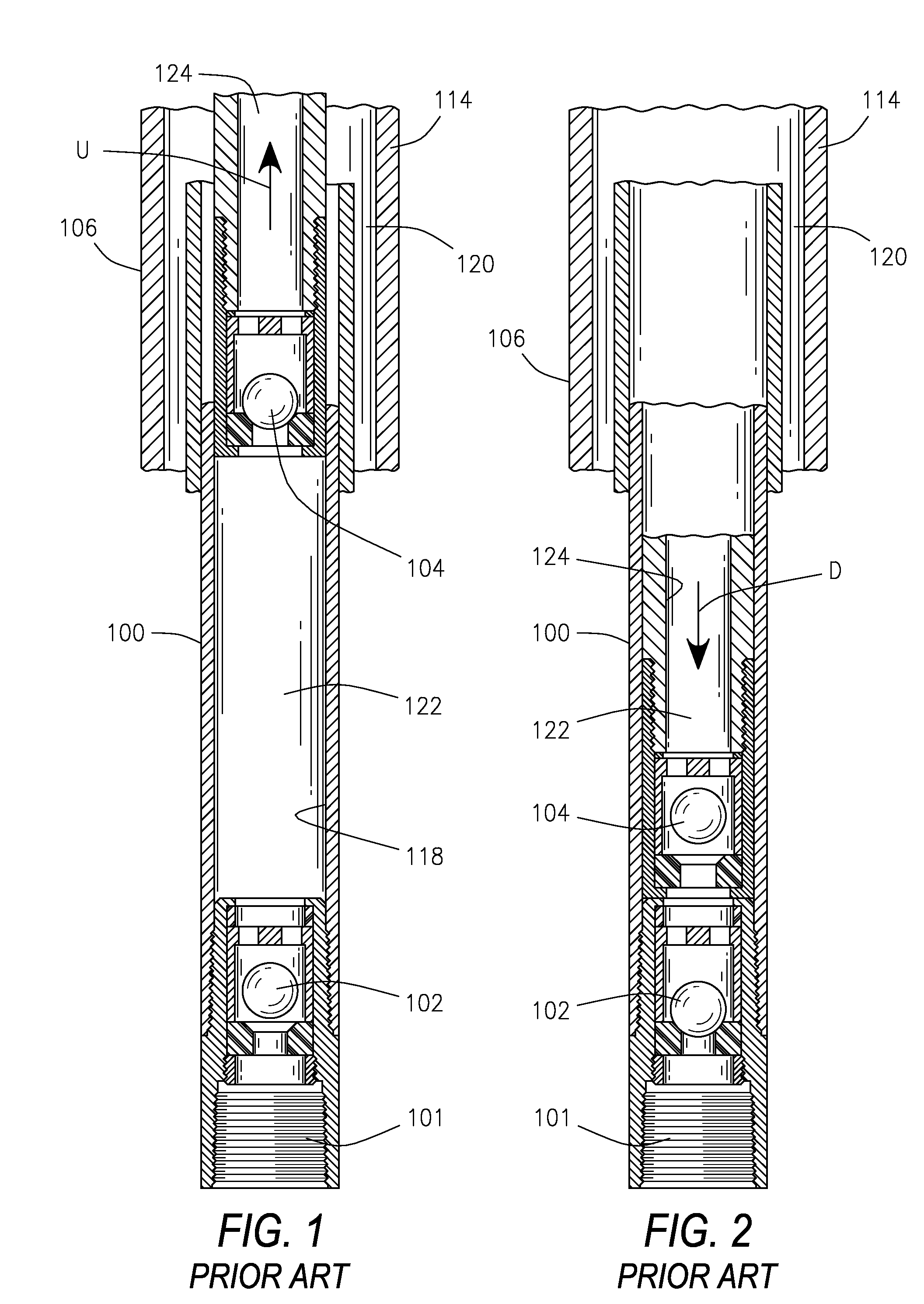
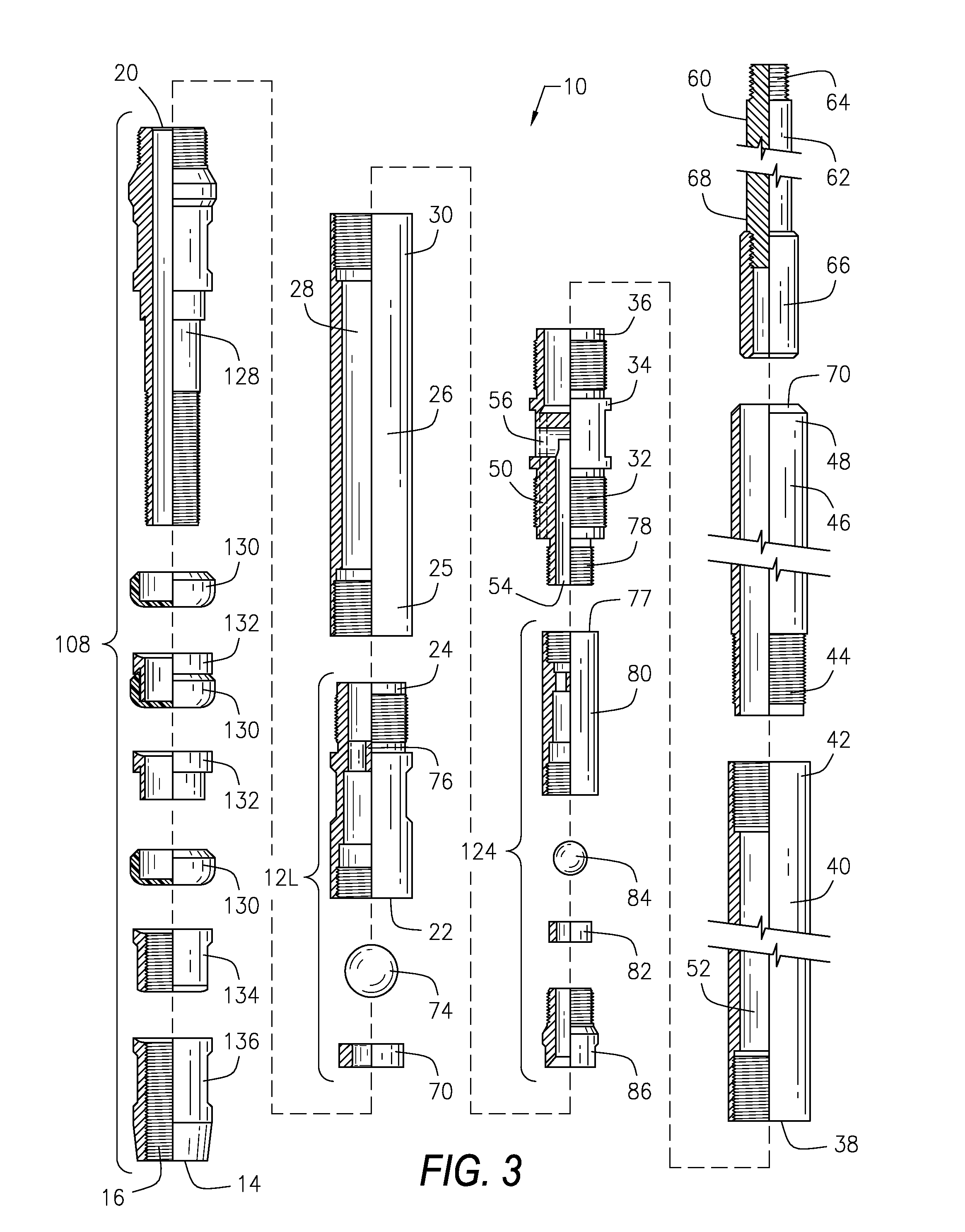
[0033]Referring initially to FIGS. 1 and 2, prior art pumps 100 that are employed to remove water 122 from gas producing coal bed wells 114 utilize a combination of a standing valve 102 and a traveling valve 104. Hereafter water 122 will be generically referred to as fluid 122.

[0034]Although not illustrated in FIGS. 1 and 2, a hold down device 108 similar to the one illustrated in FIGS. 7 and 8 threads to the bottom 101 of the standing valve 102 of the prior art pump 100. The hold down device 108 secures the prior art pump 100 to the well tubing 106 by removably engaging a seating shoe 110 provided on the tubing 106. Thus the standing valve 102 remains stationary at the bottom 112 of the well 114 while in service.

[0035]Referring again to FIGS. 1 and 2 in conjunction with FIGS. 7 and 8, the traveling valve 104 of the prior art pump 100 attaches to the rod string 116 and moves in a reciprocating manner at the bottom 112 of the well 114 in conjunction with the up and down movement of t...


PUM


Abstract

A sucker rod pump with no travelling valve consisting of, from the bottom: hold down with pump inlet, lower standing valve, hollow coupling, upper standing valve suspended within the coupling, relief valve, hollow pump housing, solid piston within the housing, and barrel to clean and retain the piston in the housing. The piston attaches to and reciprocating with the rod string. Peripheral channels in the relief valve communicate between the coupling and the housing. A central channel in the relief valve communicates between the upper standing valve and the pump's outlets. The upstroke pulls fluid from the bottom of the well upward through the open lower standing valve, around the closed upper standing valve and into the housing chamber. The down stroke pushes fluid from the housing chamber past the closed lower standing valve and through the open upper standing valve to the pump's exit into the tubing.

Description

BACKGROUND OF THE INVENTION[0001]1. Field of the Invention[0002]The present invention is a sucker rod pump that employs double standing valves and does not have a traveling valve. Specifically the present pump is particularly suited for use in gas producing coal bed wells to pump off excess water from the well so that gas can be produced, although the pump is not limited to this use.[0003]2. Description of the Related Art[0004]Gas producing coal bed wells also produce water. This water must be removed from the wells so that the wells can continue to produce gas. Prior art pumps that are employed to remove this water from the wells utilize a combination of a standing valve and a traveling valve. The standing valve attaches to the tubing via a hold down device provided on the pump that engages a seating shoe on the tubing. Thus the standing valve remains stationary at the bottom of the well while in service. The traveling valve is attached to the rod string and moves in a reciprocatin...

Claims


Application Information

Patent Timeline
IPC IPC(8): F04B53/10F04B47/00
CPCE21B33/038F04B47/026E21B43/127
Inventor FISHER, CHARLES GENE
Owner THOMPSON PUMP
Why Eureka
Try Eureka