Base station and interference reduction method in base station

a technology of interference reduction and base station, which is applied in the direction of power management, electrical equipment, network traffic/resource management, etc., can solve the problems of limiting the radio resources of adjacent cells, unable to control the interference signal power of adjacent cells, and signals become interference signals for adjacent cells. to achieve the effect of reducing interference power

Inactive Publication Date: 2010-08-26
FUJITSU LTD
View PDF10 Cites 47 Cited by
  • Summary
  • Abstract
  • Description
  • Claims
  • Application Information

AI Technical Summary

Benefits of technology

[0013]In light of the above, an object of the invention is to reduce interference power from adjacent cells.
[0015]A further object of the invention is to discriminate mobile terminals which exist at a cell border and generate strong interference signals, and, by reducing interference signals from the mobile terminals, to reduce the interference powers.
[0016]A further object of the invention is to improve the overall throughput of the system, by executing control to reduce interference signals imparted to base stations of adjacent cells by mobile terminals communicating with each base station.
[0021]Further, the above problems are resolved by a base station which performs communication with mobile terminals existing within a subordinate cell, while also executing control to reduce interference from mobile terminals existing within adjacent cells.

Problems solved by technology

In a mobile CDMA system comprising a plurality of cells as described above, signals transmitted by a mobile terminal to a connected base station (uplink signals or reverse-like signals) arrive at the base stations of adjacent cells also, and when the same frequency band is being used in uplinks between cells, such signals become interference signals for adjacent cells as a result.
On the other hand, a mobile terminal in a cell governed by a base station which is receiving interference from an adjacent cell also provides interference to the adjacent cell, and limits the radio resources of the adjacent cell.
That is, a base station can control received signal power from mobile terminals within a subordinate cell, but cannot control interference signal power from adjacent cells.
However, when there are no empty bands, the problem cannot be resolved by the base station, and so the higher-level device relative to the base station is notified of the interference information (interference occurrence, time of interference occurrence).
However, this technology of the prior art does not reduce interference imparted to the base station of a cell of interest due to uplink signals from mobile terminals in cells adjacent to the cell of interest, and in particular from mobile terminals existing in proximity to the edge of the adjacent cells.

Method used


Image

  • Base station and interference reduction method in base station
  • Base station and interference reduction method in base station
  • Base station and interference reduction method in base station

Examples


first embodiment

(A) First Embodiment

[0041](a) Network Configuration

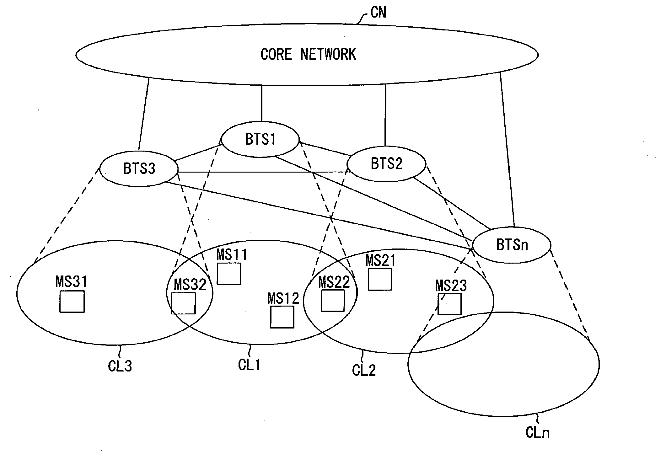
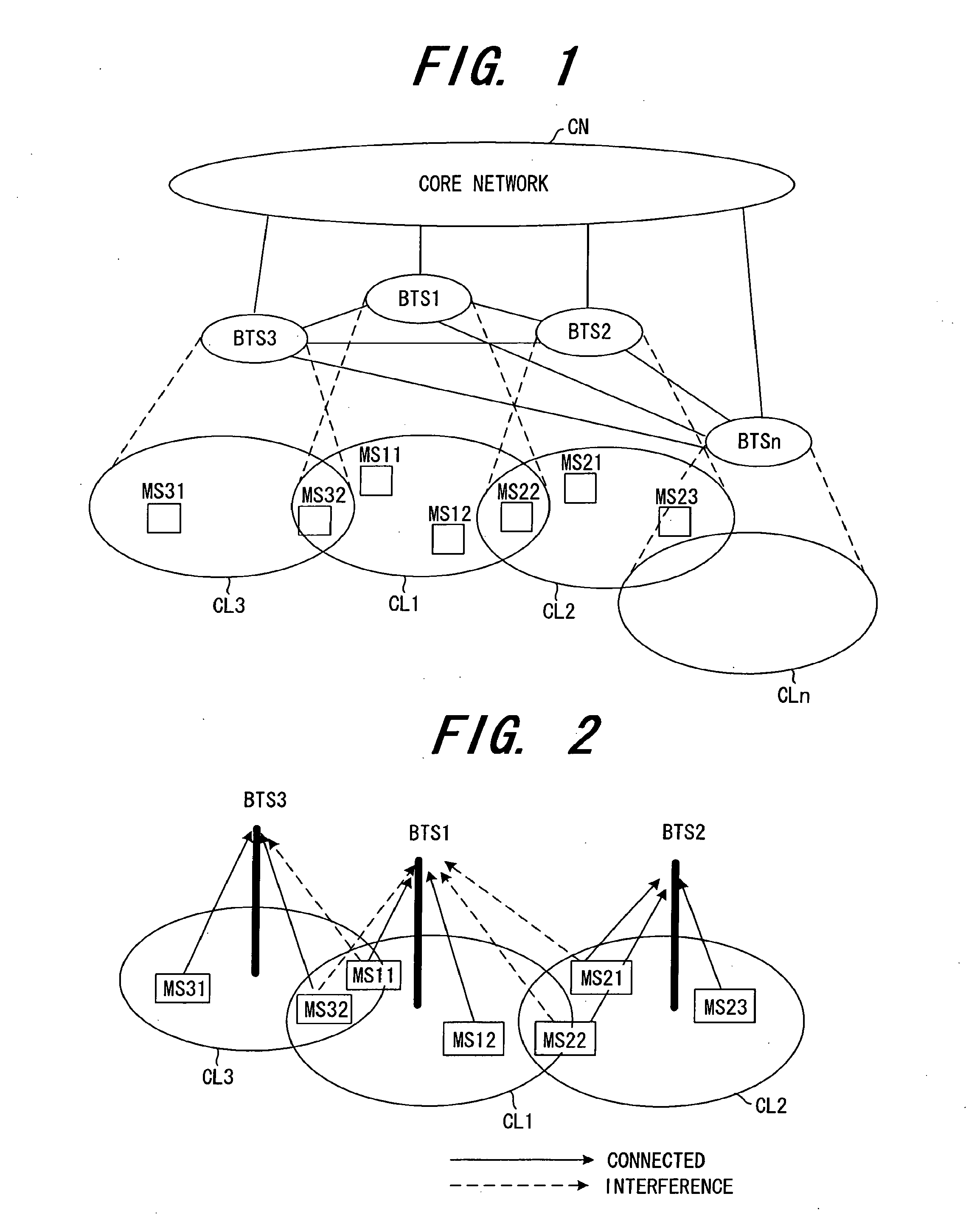
[0042]FIG. 1 shows a network configuration to which the invention can be applied; numerous base stations BTS1 to BTSn are connected to a core network CN, and the base stations can communication with mobile terminals MSij within cells CL1 to CLn. The core network CN comprises the functions of both the core network shown in FIG. 14, and a radio network controller. The base stations are connected by wire (or, for example, wirelessly using the microwave band) with adjacent base stations, and comprise interfaces for mutual communication. The network configuration of FIG. 1 is for example a network as proposed by 3GPP TR 25.897 V0.3.0 (2003-08).

[0043]FIG. 2 shows a situation in which, in three cells CL1 to CL3, mobile terminals MS2j and MS3k in adjacent cells CL2 and CL3 impart interference to the base station BTS1 of the cell CL1 of interest. In FIG. 2, three cells are shown in order to facilitate the explanation. In these three cells, t...

second embodiment

(B) Second Embodiment

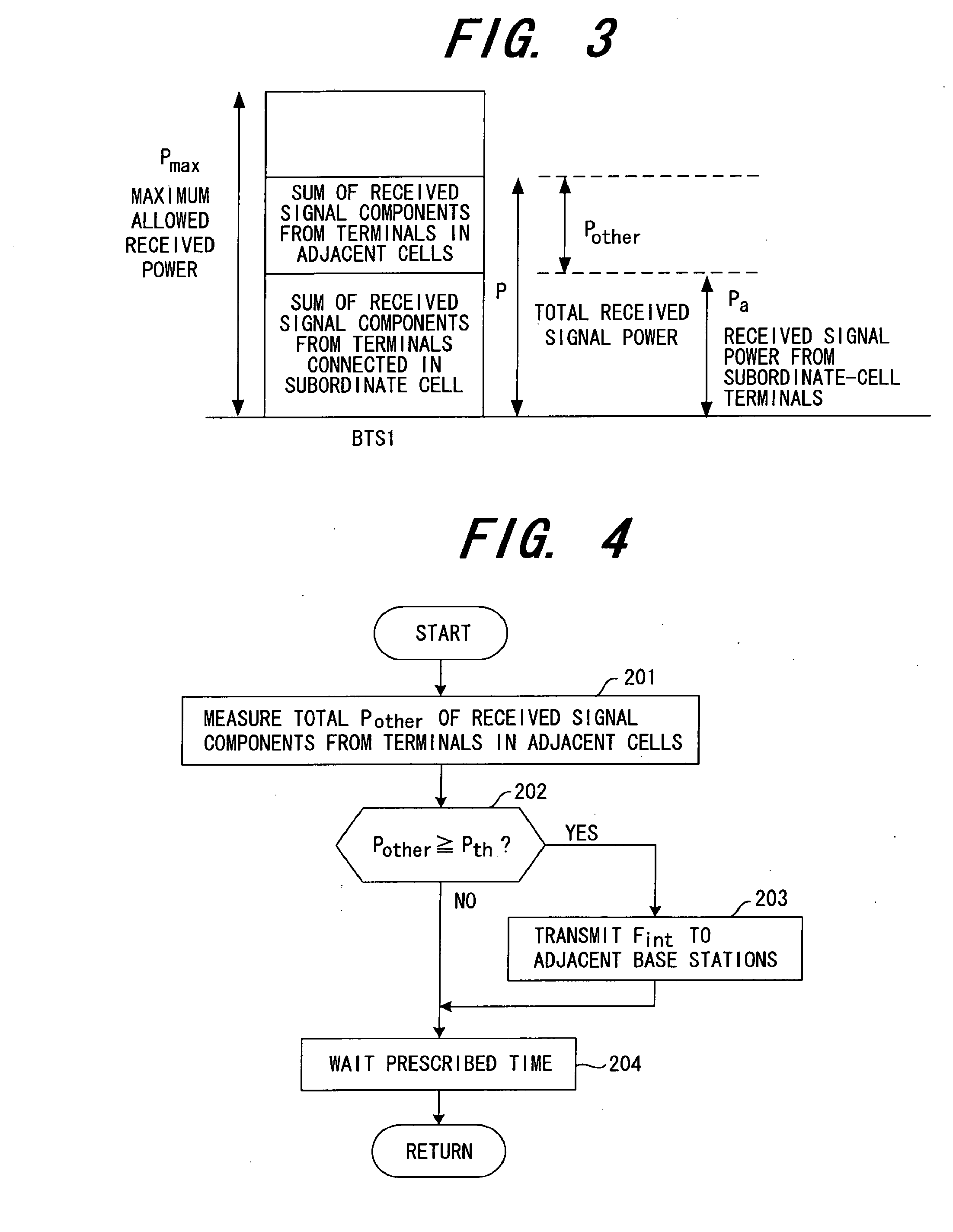
[0080]In the first embodiment, the total received signal power from mobile terminals in all adjacent cells (the total adjacent received signal power) Pother was measured based on equation (1). In a second embodiment, as shown in FIG. 10, the total received signal powers from mobile terminals in a cell (adjacent received signal power) Pcell 1 to Pcell N is measured for each cell among all adjacent cells cell 1 to cell N, and the equation below is used, that is, the adjacent received signal powers Pcell 1 to Pcell N for all adjacent cells are totaled to calculate the total adjacent received signal power Pother.

Pother=∑n=1NPcelln(2)

[0081](Here it is assumed that each mobile terminal performs scrambling using a scramble code unique to the cell before transmitting uplink data.) The adjacent received signal powers Pcell 1 to Pcell N for the adjacent cells cell 1 to cell N are measured by despreading received signals using the scramble code for each adjacent cell, and ...


PUM


Abstract

A radio communication system including mobile terminals and plural base stations each of which communicates with mobile terminals existing in a subordinate cell. Each of the base stations includes an interference power measurement portion which measures a total interference power received from mobile terminals existing in adjacent cells; an interference reduction request portion which issues a request to reduce interference to base stations of the adjacent cells based on the total interference power; and a control portion which notifies mobile terminals existing in a subordinate cell of transmission power control information when the request to reduce interference is received from a base station of an adjacent cell, so as to reduce the interference. Each of the mobile terminals includes a reception portion which receives the transmission power control information from the base station that is requested to reduce the interference from the base station of the adjacent cell.

Description

CROSS-REFERENCE TO RELATED APPLICATION[0001]The present application is a continuation of U.S. application Ser. No. 11 / 889,263, filed on Aug. 10, 2007, now pending, which is a continuation of International Patent Application No. PCT / JP05 / 0002556, filed Feb. 18, 2005, the contents of each are herein wholly incorporated by reference.BACKGROUND OF THE INVENTION[0002]This invention relates to a base station and to an interference reduction method in the base station, and in particular relates to a base station and an interference reduction method in the base station in which communication is performed with mobile terminals existing in a subordinate cell, and control is performed to reduce interference from mobile terminals existing in adjacent cells.[0003]With rapid advances in practical use of CDMA (Code Division Multiple Access) communication systems, commercial services of wideband CDMA (W-CDMA) have been begun to enable exchange of large amounts of data, including video as well as au...

Claims


Application Information

Patent Timeline
Patent Type & Authority Applications(United States)
IPC IPC(8): H04B15/00H04W24/02H04W28/18H04W72/08
CPCH04W52/243H04W52/247H04W92/20H04W72/1278H04W72/1289H04W72/1231H04W72/542H04W72/20H04W72/23
Inventor KAWASAKI, YOSHIHIRO
Owner FUJITSU LTD
Why Eureka
Try Eureka