Anti-subsidence dynamic hip screw

a hip screw and dynamic technology, applied in the field of anti-subsidence dynamic hip screw, can solve the problems of superior cut-out of lag, excessive femoral head collapse, etc., and achieve the effect of reducing the subsidence of the femoral head and being easy to assembly

Inactive Publication Date: 2010-08-26
NATIONAL YANG MING UNIVERSITY +1
View PDF8 Cites 14 Cited by
  • Summary
  • Abstract
  • Description
  • Claims
  • Application Information

AI Technical Summary

Benefits of technology

[0010]According to above structure, it is not only easy to assembly, especially for the effect of decreasing the subsidence of the femoral head, but also makes the effect more obvious when using for the hip fracture of the osteoporosis body.

Problems solved by technology

However, when the screws of above patents disclosed is used in the osteoporosis patients, the bone mass of the femoral head is too low and results in the femoral head collapsing excessively so that the contact area between the lag screw locked in the femoral head and the bone is too small and further results in the complications of superior cut-out of the lag screw
However, the contact area between the tang legs and the femur is not large enough, and then it is not obvious to fix the lag screw to the femoral head when encountering the situation of above mentioned that the femoral head collapses excessively because the bone mass is too low.
However, the depth of each pin implanting into the femur is limited.
Therefore, the effect of the subsidence relative to the femoral head is limited, too.

Method used


Image

  • Anti-subsidence dynamic hip screw
  • Anti-subsidence dynamic hip screw
  • Anti-subsidence dynamic hip screw

Examples


Embodiment Construction

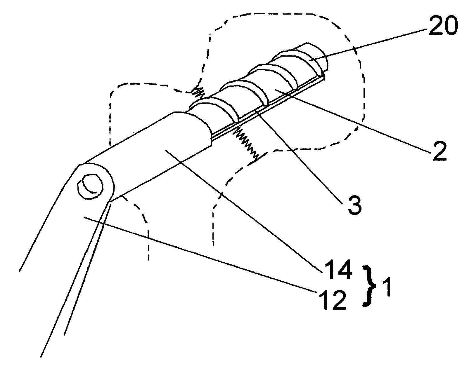
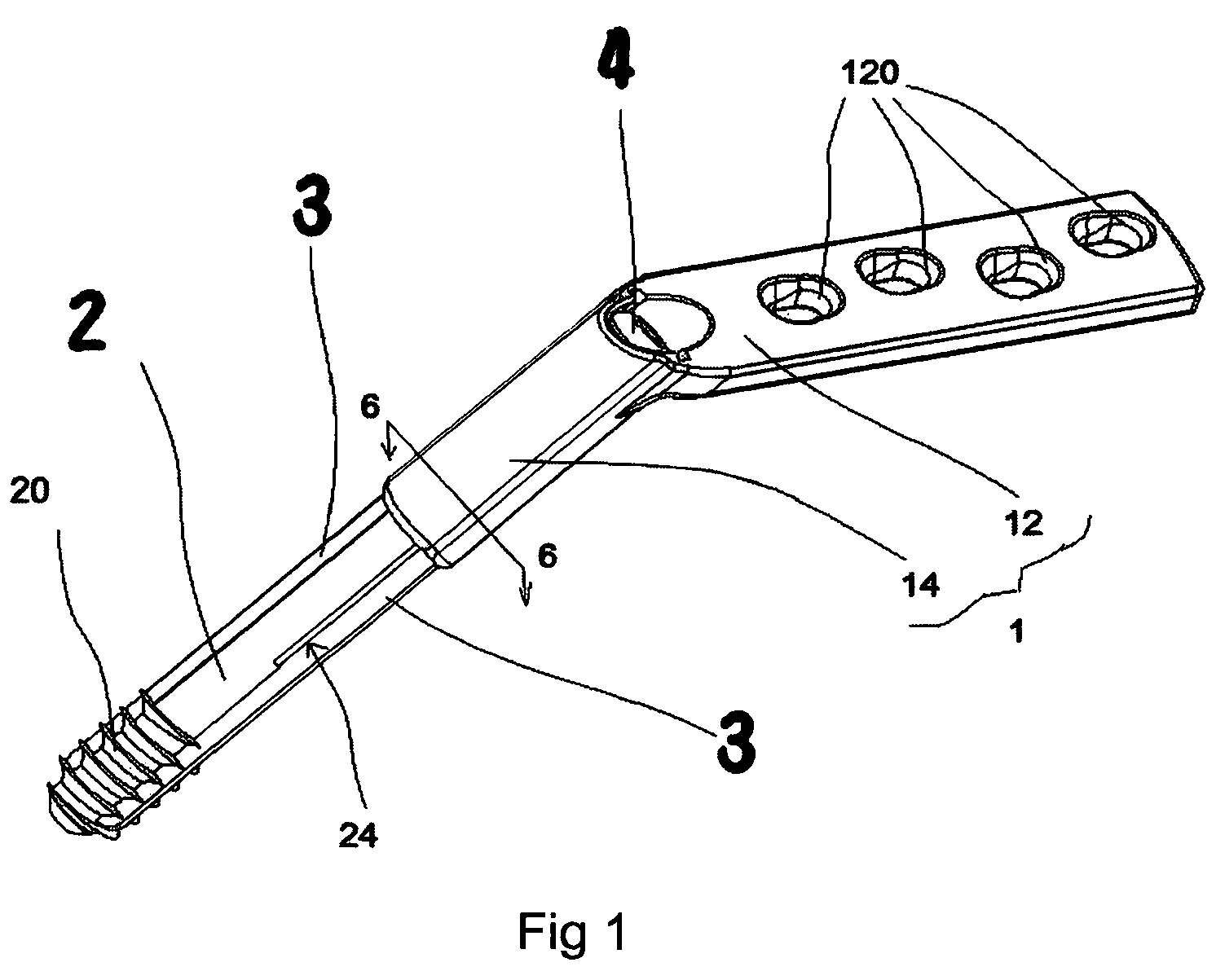
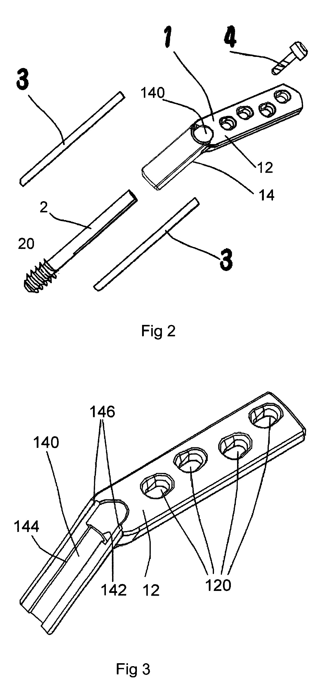
[0020]Referring now to the drawings where like characteristics and features among the various figures are denoted by like reference characters. The present invention is disclosed a dynamic hip combination structure used for reconstructing the femoral head fractures, which mainly comprises of a barrel 1, a lag screw 2, two blade piece 3 and a compressing screw 4.

[0021]The barrel 1, as shown in FIG. 1 to FIG. 4, has a connection portion 12 which the inside of the connection portion 12 is a concave arc surface for increase the contact area of the connection portion 12 and the outer edge of a femur when setting the connection portion against the outer edge of the femur, and four through holes 120 is passed through the inside and outside of the connection portion 12 and spaced apart an adaptive distance; and an extending portion 14 is tube type with an adaptive length, which the outer edge of the outside end of the extending portion 14 is connected with the upper end of the connection po...


PUM


Abstract

An anti-subsidence dynamic hip screw comprises of a barrel having a connection portion and a tube-type extending portion angled a predetermined angle with the connection portion, and a first long groove and a first limit portion disposed at the inner wall of the extending portion respectively; a lag screw having an inside end disposed threading screw at its outer edge and a outside end with a predetermined length passed through in the extending portion by the way of reciprocation; a second long groove and a second limit portion disposed at the lag screw respectively related to the first long groove and the first limit portion, each first limit portion and second limit portion used for preventing the lag screw from rotating inside the extending portion; a blade piece with a predetermined length simultaneously passed through and retained in the first long groove and the related second long groove; a compressing screw having an inside end screwed with the outside end of the lag screw and an outside end retained in the outside end of the extending portion. The above structure is not only easy to assembly, especially for the effect of decreasing the subsidence of the femoral head, but also makes the effect more obvious when using for the hip fracture of the osteoporosis body.

Description

BACKGROUND OF THE INVENTION [0001]1. Field of the Invention[0002]The present invention generally relates to an anti-subsidence dynamic hip screw, and more particularly to an anti-subsidence dynamic hip screw capable of decreasing the subsidence of the femoral head when using for reconstructing and resetting femoral fractures.[0003]2. Description of the Related Art[0004]Clinically, the proximal femoral fracture is one of the common diseases and occurred in the eldly and the population of the osteoporosis. Because the osteoporosis results in the fractures of the femoral neck or greater trochanter of the hip joint, it is usually used the dynamic hip screw or compression hip screw to reconstruct and reset the fracture.[0005]The design of conventional compression hip screw emphasizes on enhancing the lock of the screw (disclosed by U.S. Pat. No. 4,973,333 and U.S. Pat. No. 5,041,116), preventing the rotation of the femoral head (disclosed by U.S. Pat. No. 4,657,001), or providing the bet...

Claims


Application Information

Patent Timeline
Patent Type & Authority Applications(United States)
IPC IPC(8): A61B17/56
CPCA61B17/8685A61B17/746
Inventor CHEN, TAIN-HSIUNGCHENG, CHENG-KUNGWEI, HUNG-WENLAI, YU-SHUYU, PING-SHENG
Owner NATIONAL YANG MING UNIVERSITY
Why Eureka
Try Eureka