Implant, implantation tool, kit and method

a technology of implantation tools and implants, applied in the field of implants, can solve the problems of insufficient pull-out strength, slow fastening, and high temperature of the tissue around the fastening means, and achieve the effects of avoiding tissue damage caused by high temperature, fastening very quickly, and firm pull-out strength

Active Publication Date: 2010-08-26
INION
View PDF14 Cites 23 Cited by
  • Summary
  • Abstract
  • Description
  • Claims
  • Application Information

AI Technical Summary

Benefits of technology

[0014]An advantage of the implant, tool and kit of the invention is that the implant may be fastened to a tissue very quickly. It is still possible to achieve a firm pull-out strength with the implant. Another advantage is that the temperature at the interface between the implant and the tissue remains low during the entire fastening process, and tissue damages caused by a high temperature can be avoided.
[0015]The idea of a preferred embodiment of the invention is that certain parts of the implant, but not the whole implant, are heated to a suitable transition temperature, such as a Tg temperature or an orientation temperature, wherefore the above-mentioned mechanical loading or shaping of the implant may be performed more quickly. In this way, it is possible to fasten the implant even more quickly.

Problems solved by technology

A problem with screws is, however, that the fastening is slow.
A problem with pins is, in some cases, an insufficient pull-out strength.
A problem with this solution is that the temperature of the tissue around the fastening means may rise so high that the tissue will be damaged.
Problems here include the above mentioned heating of tissues and a relatively weak pull-out strength.

Method used


Image

  • Implant, implantation tool, kit and method
  • Implant, implantation tool, kit and method
  • Implant, implantation tool, kit and method

Examples


example 1

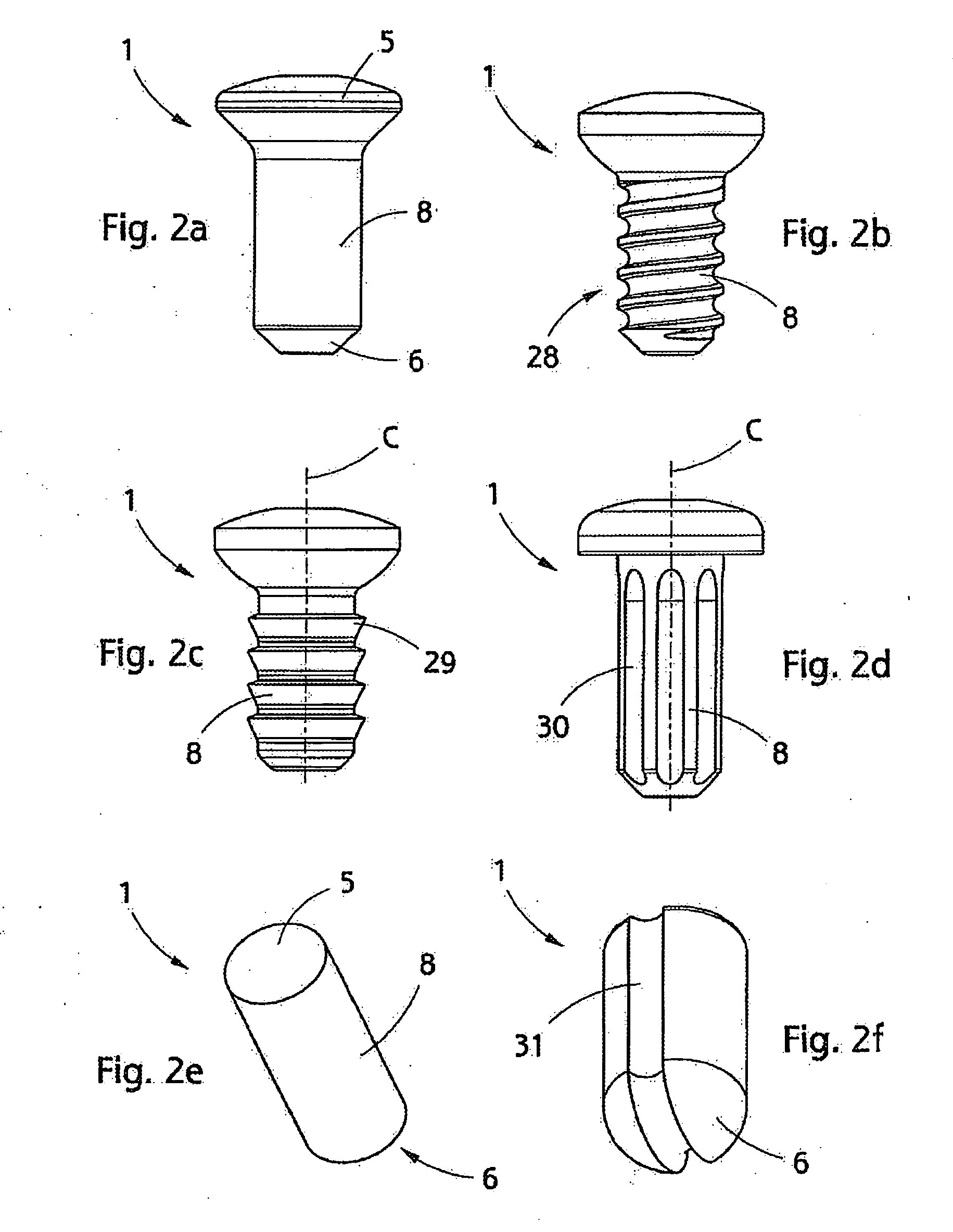
[0084]An implant according to FIG. 2e made of an oriented polymer with a draw ratio 4 was heated at a steady temperature in an oven for different times and dimensional changes were examined as a function of time. The outer diameter of the implant was approximately 4 mm.

[0085]It was found that a significant radial swelling took from dozens of seconds to few minutes, which was too much for practical applications. It was also found that the swelling took place at physiologically too high a temperature (70 to 90° C.).

[0086]It was also detected that the heat-induced swelling of the implant arranged in a loose mounting hole in the bony tissue stops at the wall of a bore channel. The pull-out strength achieved with the implant was marginal, below 50 N, and the produced surface pressure against the bone was approximately 1 MPa.

[0087]In addition, both oriented and non-oriented implants were mounted by inserting the implant into a tightly-dimensioned mounting hole provided in the bone and hea...

example 2

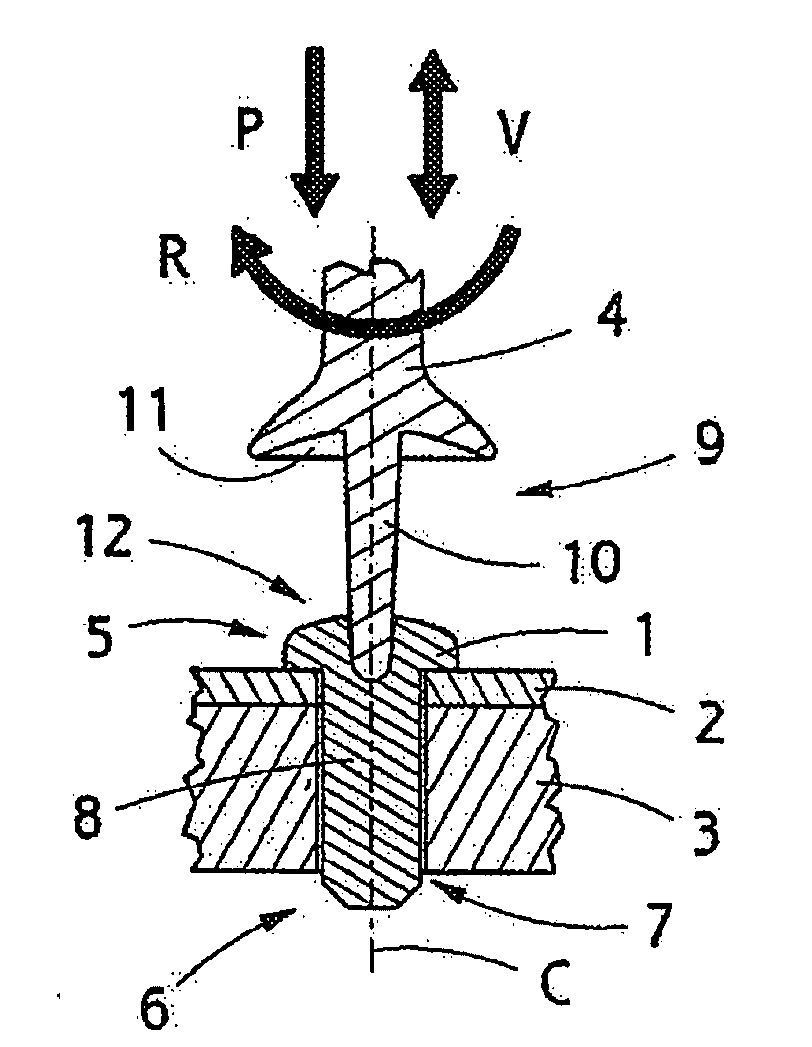
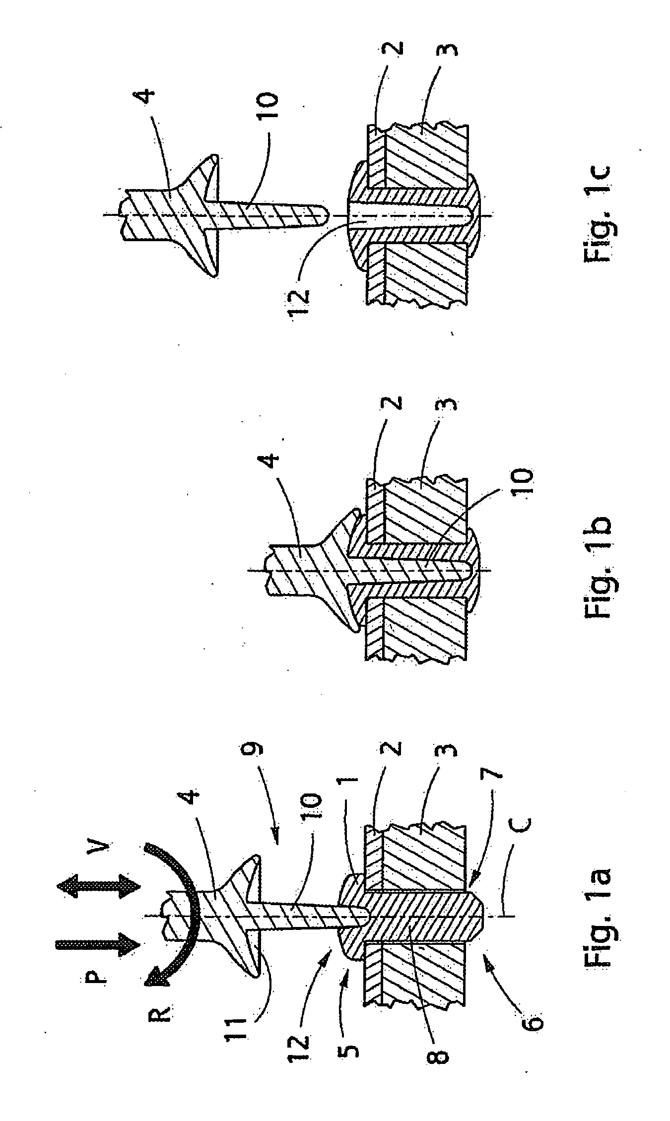
[0088]An implant of FIG. 3f made of an oriented material was arranged in a tightly-dimensioned mounting hole provided in the bone. The implant was forced to expand sideward towards the bone by inserting a hot pin 10 wider than the diameter of the hole 12 into the hole 12 of the implant. The implant expanded in few seconds, which was, in terms of clinical use, very quickly. As a result of the heating, a temperature gradient was formed at the implant, i.e. the shank thereof, whereby the temperature of the inner section of the implant, i.e. the shank part closely surrounding the hole 12, was 100 to 150° C., whereas the temperature of the outer surface against the tissue remained below 48° C. In other words, the temperature of the inner section of the implant was above the Tg temperature and / or orientation temperature of the manufacturing material of the implant and the temperature of the outer surface was below the Tg temperature so that temperature-induced cell damages could be avoide...

example 3

[0091]A non-oriented implant of FIG. 3f was arranged in a bone in the manner described in Example 2. By mechanically shaping or forcing the implant, such an implant also provided completely sufficient pull-out strength values in pull-out tests.

[0092]Depending on the application, non-oriented material may also be considered to be used, but it is advantageous to minimize the amount of foreign matter in the body and to use an oriented, stronger polymer whenever there is no other obstacle to use it.


PUM


Abstract

An implant to be fastened to a tissue, a tool a kit and a method. The implant has a first end, a second end and an elongated shank made at least partly of a first polymer material. The implant comprises a contact surface for receiving external mechanical energy for deforming the shape of the implant such that the shape of the implant can be deformed and locked in the tissue by the effect of said mechanical energy.

Description

RELATED APPLICATION[0001]This application claims priority from European patent application number 09100138.8, filed Feb. 23, 2009 which is hereby incorporated herein by reference in its entirety for all purposes.FIELD[0002]The present invention relates to an implant to be fastened to a tissue, the implant having a first end, a second end and an elongated shank made at least partly of a first polymer material.[0003]The present invention further relates to an implantation tool for fastening an implant to a tissue, the implant being made at least partly of a first polymer material, the tool comprising a body and shaping means arranged at said body.[0004]The present invention further relates to a kit for fastening a material to a tissue.[0005]The present invention further relates to a method for fastening a material to a tissue.BACKGROUND[0006]In the prior art, screws and pins, for example, are used for fastening implants to a tissue. A problem with screws is, however, that the fastenin...

Claims


Application Information

Patent Timeline
Patent Type & Authority Applications(United States)
IPC IPC(8): A61B17/58A61B17/86
CPCA61B17/0401A61F2210/0071A61B17/80A61B17/846A61B17/864A61B17/866A61B17/8863A61B2017/00004A61B2017/0408A61B2017/0409A61B2017/0422A61F2/0811A61F2002/0835A61F2002/0852A61F2002/0864A61F2002/0888A61F2002/30065A61B17/683A61C8/005A61C8/0054
Inventor HELEVIRTA, PERTTIHAPPONEN, HARRIPOHJONEN, TIMOKRUUSING, ARVI
Owner INION
Why Eureka
Try Eureka