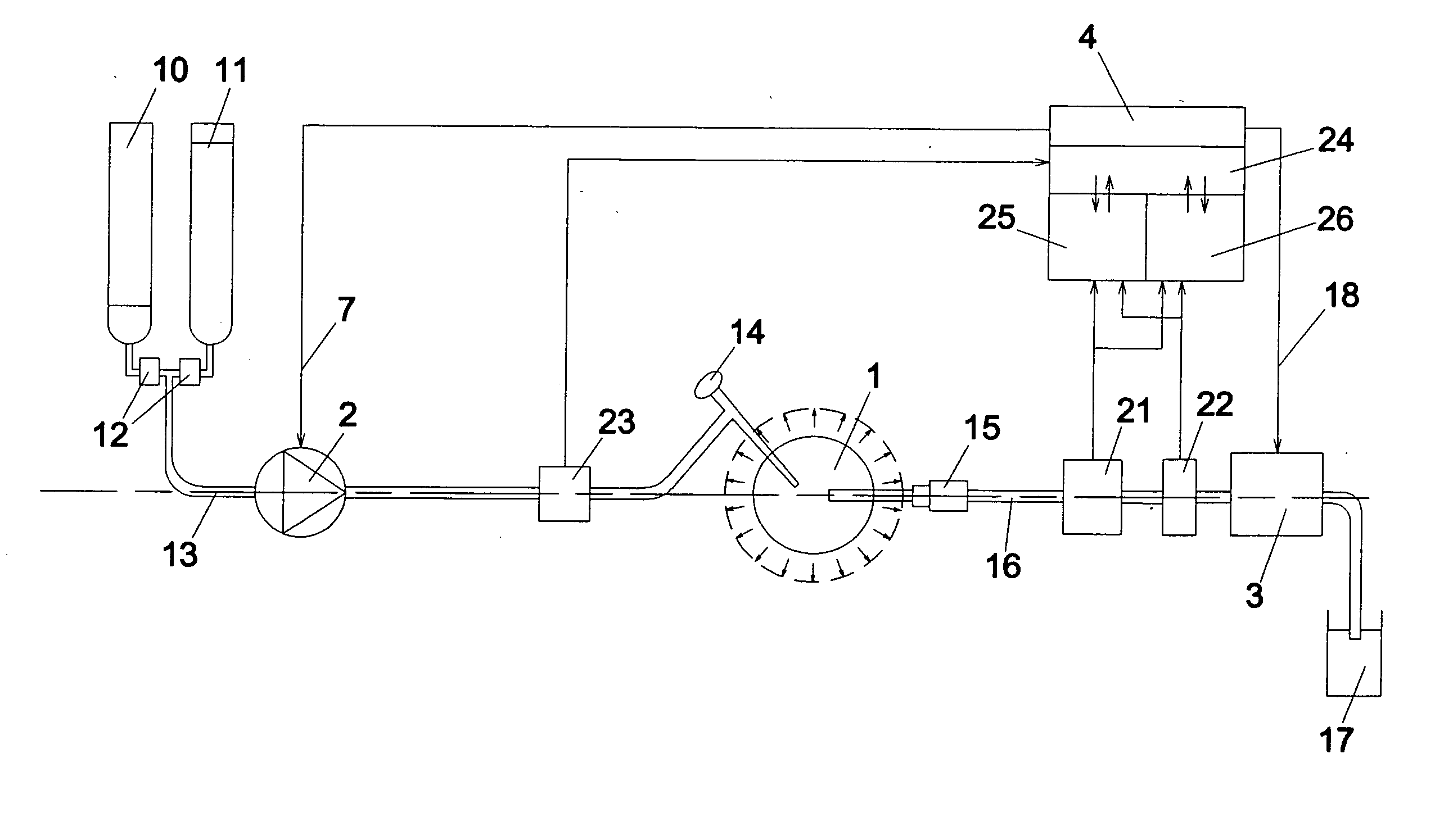
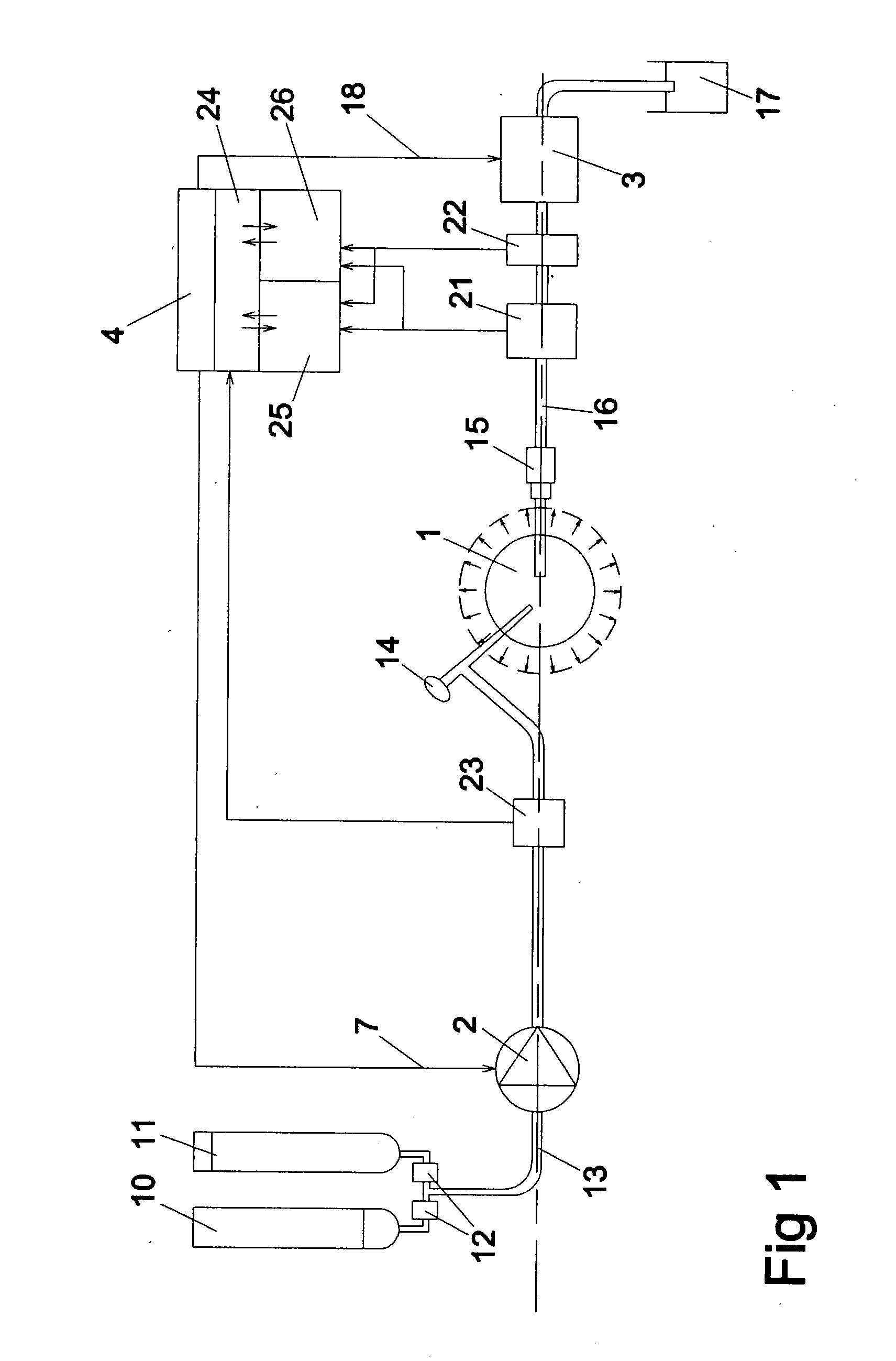
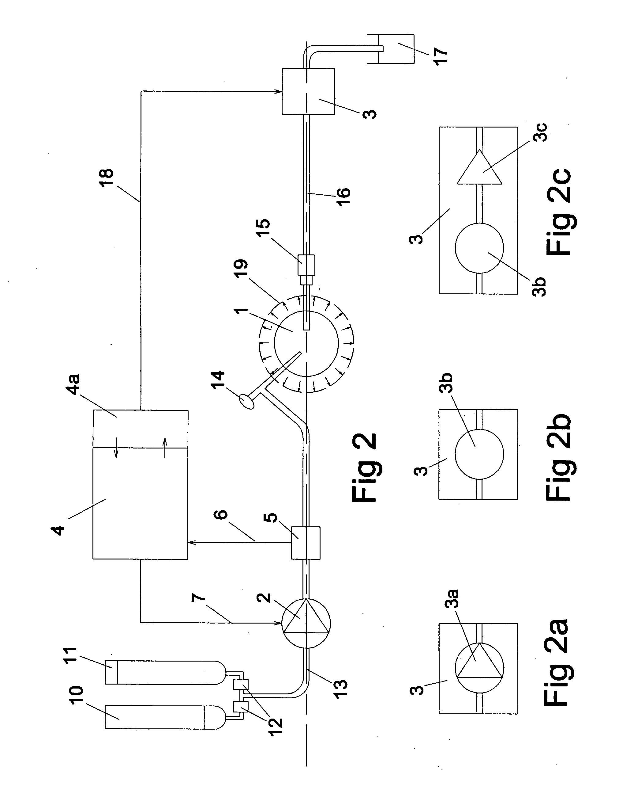
[0018] Secondly, the resistance in the system is reconfirmed during routine use of the system. This reconfirmation is made by a temporary halt of flow by stopping both the inflow and outflow pumps instantaneously. The outflow pump can alternatively be replaced with a valve, which stops the flow in the same manner. This alternative can be used when the liquid
management system only operates an irrigation pump. The valve function may comprise means to pinch tubing. At that instant, the pressure is high at the inflow pump, where the pressure is also measured, and lower in the body cavity. The liquid is trapped between the following components: the roller of the inflow
peristaltic pump; the cavity of the pressure
transducer; the tubing from the pressure
transducer to the
endoscope connector with shutoff valve;
endoscope connector with shutoff valve; the endoscope; the body cavity; the liquid output from the body cavity such as a cannula, shaver or other instrument; the tubing from the output instrument to the rollers of the outflow
peristaltic pump, or a valve function; and finally the rollers of the outflow
peristaltic pump or a valve function. During the next phase, being approximately 2 seconds, the
pressure difference between the inflow pump and the body cavity causes a diminishing flow to the body cavity. If the time the pumps are stopped is long enough, the
pressure difference will diminish by a basic rule of
communicating vessels. The
time constant of this diminishing flow is a representation of resistance. It is to be noted that it is not necessary to hold the pumps stopped for the time it takes for the flow to become zero. An extrapolation of the pressure
signal is fulfilling for the purpose of determining an end pressure. This minimizes the time the body cavity is not irrigated. The reconfirmation can be initialized manually by pressing a button, or automatically by regular intervals controlled by the
software, or automatically triggered by
software if pressure fluctuations occur that indicate that the surgical situation might have influenced resistance.
[0021] Compliance values can be calculated by the pump system, which measures the pressure as mentioned above, and the flow is proportional to the rotational speed of the roller pump heads. Calculated compliance values are also stored in a memory, and can be used in several ways. One first consideration is the effect the compliance has on the process of reconfirmation of resistance values. The reconfirmation of resistance values is adjusted for as a result of the compliance as the aforementioned
time constant is affected by compliance. Another use of the compliance value is to indicate these to the operator. This has the benefit of warning the operator of the risk that excessive liquid may be introduced. The indication can be that of a figure in a display, a “bar indicator” in a display, or a
buzzer that emits sound at a predetermined level of compliance. The compliance value can also affect the operation of the pump system by limiting the pressure it produces, to avoid
tissue damage.
[0031] Rinsing of the body cavity may be initiated manually by the press of a button or a foot operated switch, and results in an increased liquid flow. However the detection of blood or debris may automatically initiate a rinsing process. This detection may in general increase flow through the body cavity and this will beneficially keep the liquid clear. Such increase may be gradual or in steps to achieve the target of a clear viewing filed for the surgeon. Whether decided by a user or automatically by the system, the rinsing of the body cavity can be terminated manually or automatically. Optionally the pressure may be elevated to depress bleeding. This elevation of pressure is preferred as blood is detected, but not debris. Increasing pressure over the patients'
perfusion blood pressure reduces the bleeding. The result is that a clear viewing field is maintained automatically and the operator can focus on the
endoscopic procedure instead of manually optimizing the liquid
management system to give
visibility. The
operation time will thereby be reduced in most procedures resulting in fewer complications for the patient.

