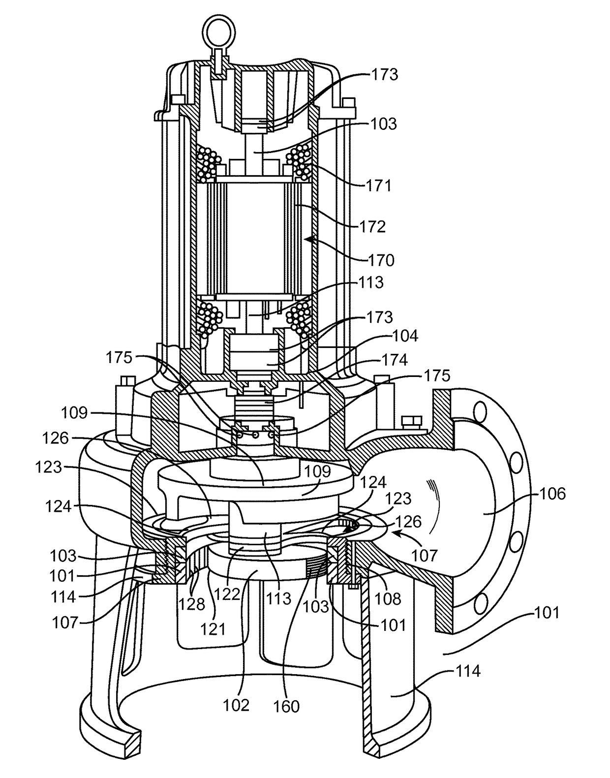
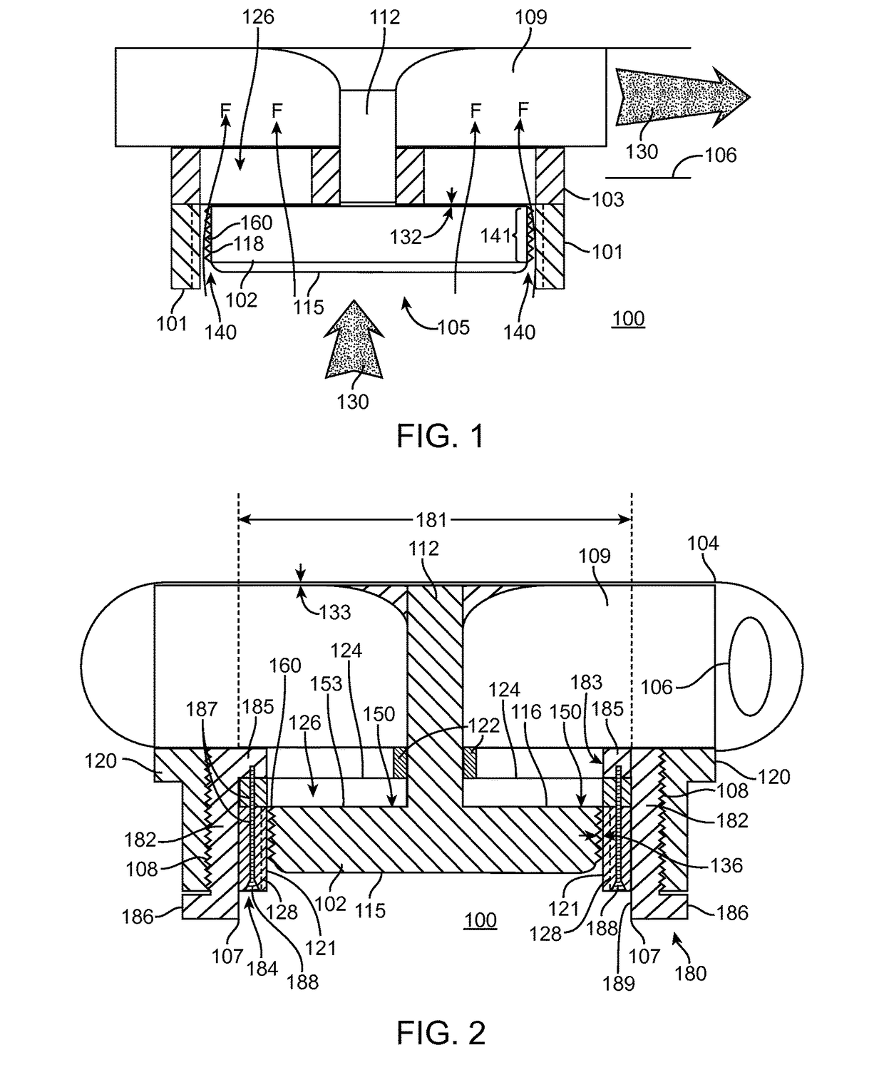
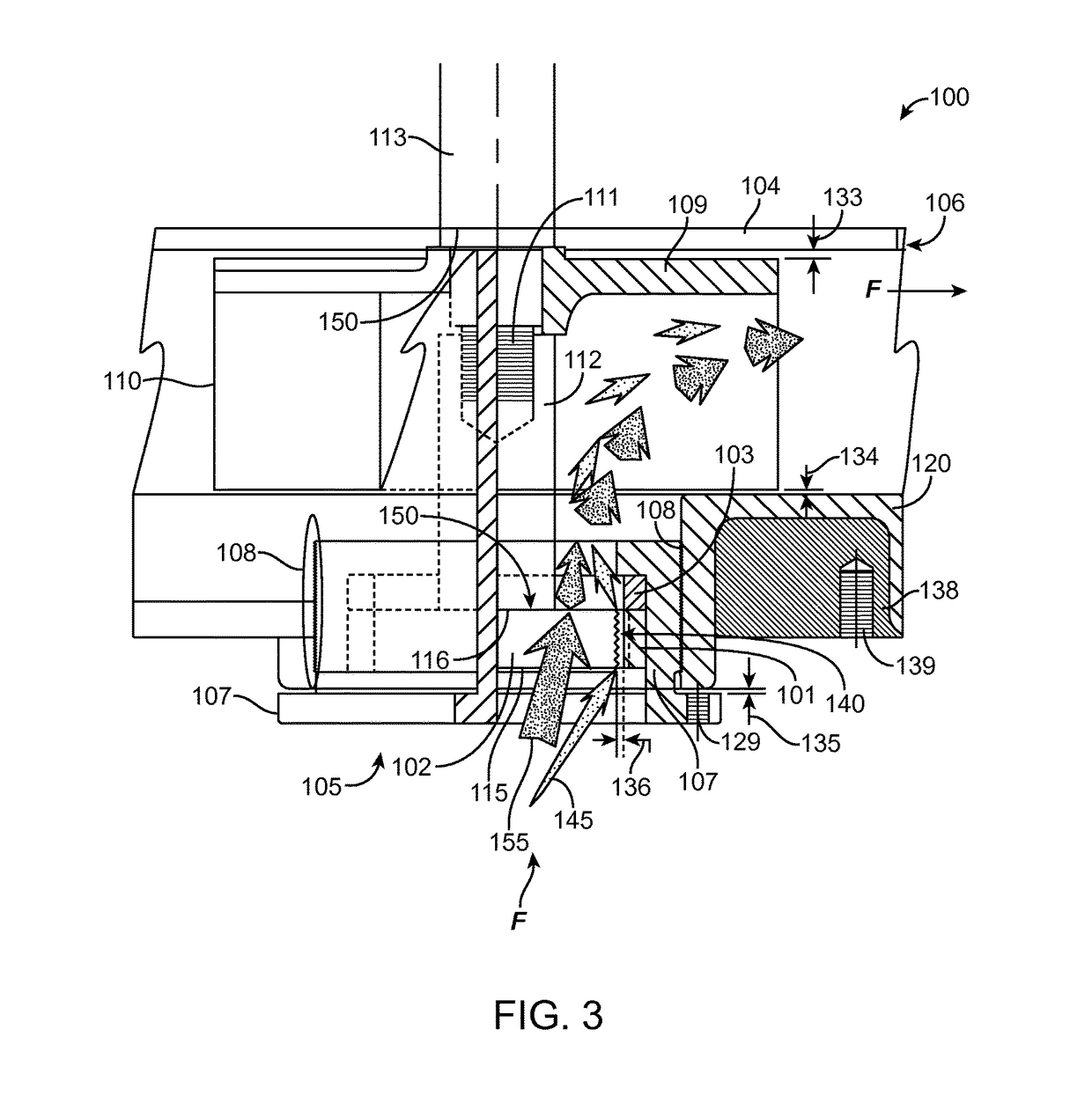
Shred and shear pump

a technology of shear pump and solids, which is applied in the field of pumps, can solve the problems of pump failure, reduced pump output flow, and poor shredding effect of conventional pump design, and achieve the effect of improving liquid flow

Active Publication Date: 2017-08-01
IND FLOW SOLUTIONS OPERATING LLC
View PDF9 Cites 3 Cited by
  • Summary
  • Abstract
  • Description
  • Claims
  • Application Information

AI Technical Summary

Benefits of technology

[0011]The shred and shear pump of the present invention may be formed with an adjustable interface between the surface of the axial cutter ring and the cutter bar to allow for optimal shearing cutting action when new and for adjustments later to maintain optimal shearing cutting action after some wear has occurred (i.e., to adjust the gap between cutter bar and axial cutter ring assembly to compensate for wear, thereby allowing for a longer service of the pump).
[0013]The openings formed by the one or more blades of the axial cutter ring assembly are configured so as improve liquid Flow F and the passage of solids from the inlet to the outlet of a smaller profile shred and shear pump so as to perform in applications where larger non-clog wastewater pump are currently utilized.

Problems solved by technology

While these pumps can chop solids to varying degrees to permit solids to flow through to the output of the pump for disposal, other problems occur because modern wastewater contains solids in the form of synthetic disposable products and woven fibrous materials.
Conventional pump designs do a poor job of shredding such solids and woven fibrous materials.
Once balled, woven fibrous materials often fail to pass out of the pump, reduce the pump output flow, and can result in pump failure such as, for example, clogging, seizing and motor burnout.
Existing chopper pump designs have disadvantages in processing solids of woven fibrous materials including clogging, wrapping or stoppage of the pump operation because once the solids have entered the impeller, these solids must travel across to the back plate before the cutting action, whereby wrapping can occur before cutting.
Existing grinder pump designs have disadvantages including not allowing solids to gain entry until sliced into smaller particles, i.e. in an all-or-nothing action relying on the solids being cut or kicked-out before being sucked back to the impeller for another try.
The kick-out action of solids and woven fibrous materials in conventional grinder pump designs is often unsuccessful and less than optimal.
Wrapping and clogging can still occur even after multiple kick-out actions of the solids because woven fibrous materials accumulate to eventually clog the pump intake that can leading to pump failure (e.g. burnout).
However, over-sizing the pump to increase pump intake also results in a cost increase in the pump needed for the application.

Method used


Image

  • Shred and shear pump
  • Shred and shear pump
  • Shred and shear pump

Examples


Embodiment Construction

[0027]Non-limiting embodiments of the present invention will be described below with reference to the accompanying drawings, wherein like reference numerals represent like elements throughout. While the invention has been described in detail with respect to the preferred embodiments thereof, it will be appreciated that upon reading and understanding of the foregoing, certain variations to the preferred embodiments will become apparent, which variations are nonetheless within the spirit and scope of the invention.

[0028]The terms “a” or “an”, as used herein, are defined as one or as more than one. The term “plurality”, as used herein, is defined as two or as more than two. The term “another”, as used herein, is defined as at least a second or more. The terms “including” and / or “having”, as used herein, are defined as comprising (i.e., open language). The term “coupled”, as used herein, is defined as connected, although not necessarily directly, and not necessarily mechanically.

[0029]R...


PUM


Abstract

The present invention is a pump used for applications where a solid is present in wastewater and other liquids that requires cutting and reduction in size so as to pass the solid through the inlet to the outlet of the pump. The pump has a pump casing with an inlet and an outlet formed therein. A drive unit rotates a drive shaft extending axially through the pump casing to an impeller and a cutter bar. The pump is further configured with a radial cutter ring assembly positioned adjacent the cutter bar and the inlet providing a shredding cutting action of solids between the rotating cutter bar sliding past a radial cutter ring assembly held stationary, e.g. cutting blades formed in an edge of the cutter bar rotate across an internal surface of the radial cutter ring assembly. The pump also has an axial cutter ring assembly with one or more blades forming openings adapted for the passage of solids from the inlet to the outlet to provide a shearing cutting action of solids by a rotation of an upper surface of the cutter bar sliding past an axial cutting surface of the blades of the axial cutter ring assembly. The shred and shear pump may be configured with a plurality of slots on the internal surface of the radial cutter ring assembly to hold woven fibrous material for the shredding cutting action. The pump also features improved optimized flow, cutting and reducing solids in the form of woven fibrous materials, and adjustability of the cutter housing for precision and wear adjustment.

Description

[0001]This patent application claims priority to U.S. Provisional Patent Application Ser. No. 61 / 861,365 entitled “SHRED AND SHEAR CENTRIFUGAL PUMP” filed on Aug. 1, 2013, and the entire disclosure is hereby incorporated by reference herein.FIELD OF THE INVENTION[0002]The present invention is in the field of pumps capable of shearing and shredding solids at the intake of portion of the pump for numerous applications including wastewater, sewage, sewerage, industrial, and agriculture.BACKGROUND OF THE INVENTION[0003]A variety of pumps are known currently for pumping liquids, wastewater, and other liquids containing solids such as garbage, disposable products, woven fabrics, poly-materials, and other items. While these pumps can chop solids to varying degrees to permit solids to flow through to the output of the pump for disposal, other problems occur because modern wastewater contains solids in the form of synthetic disposable products and woven fibrous materials. Conventional pump d...

Claims


Application Information

Patent Timeline
Patent Type & Authority Patents(United States)
IPC IPC(8): F04D29/70F04D7/04F04D13/08F04D29/22F04D29/24F04D1/00F04D13/02F04D29/42F04D29/44
CPCF04D29/708F04D1/00F04D7/045F04D13/02F04D13/086F04D29/22F04D29/2288F04D29/24F04D29/426F04D29/448B02C18/0092
Inventor MITSCH, BRIAN M.
Owner IND FLOW SOLUTIONS OPERATING LLC
Why Eureka
Try Eureka