Mold having ceramic insert

a technology of ceramic inserts and molds, applied in the field of molds, can solve the problems of mold wear, unsatisfactory need for electrode molds, long service life, etc., and achieve the effects of reducing material loss, increasing the yield of molding process, and prolonging service li

Active Publication Date: 2014-03-06
HAYNES INTERNATIONAL
View PDF2 Cites 0 Cited by
  • Summary
  • Abstract
  • Description
  • Claims
  • Application Information

AI Technical Summary

Benefits of technology

[0014]Use of the ceramic insert eliminates all material loss from the end of the electrode covered by the insert, increasing the yield for the molding process. Additionally, a cast iron mold with a ceramic insert as disclosed here has a substantially longer service than a mold of the same size that is made entirely from cast iron.

Problems solved by technology

The pouring of hot metal into the electrode mold and the removal of the electrode causes wear on the mold.
There has been a long, unsatisfied need for electrode molds, as well as other molds used to create other metal parts, which have a longer service life and which produce less scrap.
Because the mold plates are made from wear-resistant metal alloys, conventional machining of these plates is extremely difficult, expensive, time consuming, and is also limited to machining simple mold cavity geometries.
However, as with the first method, this approach requires expensive and time consuming metal removal methods to create the cavity shape within the metal insert.
Injection molding is extremely hard on molds.
Although some ceramic inserts last longer than others, they all suffer eventually because of distortion, erosion of the mold cavity surface, heat checking from thermal shock, and for other reasons.
Materials such as abrasive resistant steels are not preferred because such materials are difficult to machine and require EDM processes.
Consequently, the use of ceramic inserts in molds for injection molding of plastics has not been considered as being transferrable to molds used in steel making.

Method used


Image

  • Mold having ceramic insert
  • Mold having ceramic insert
  • Mold having ceramic insert

Examples


Embodiment Construction

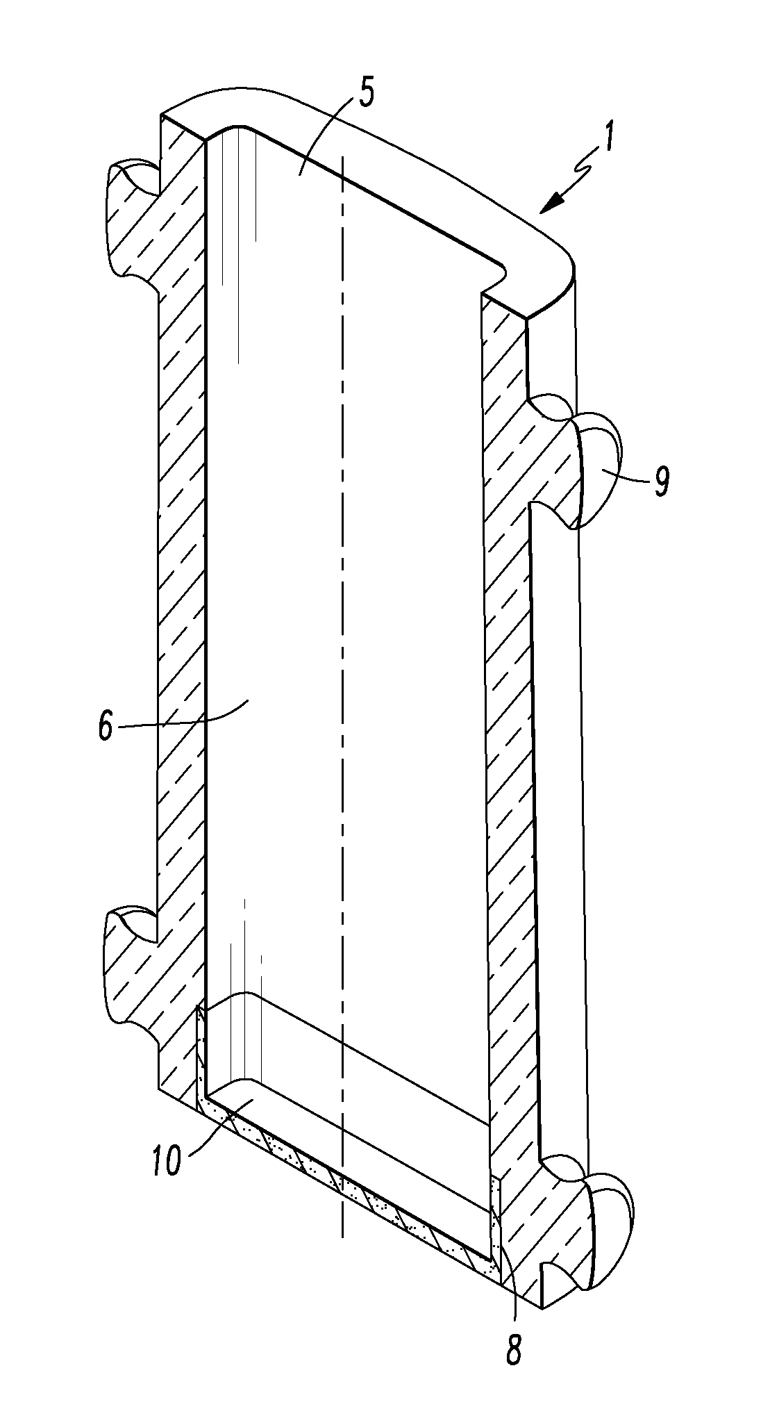
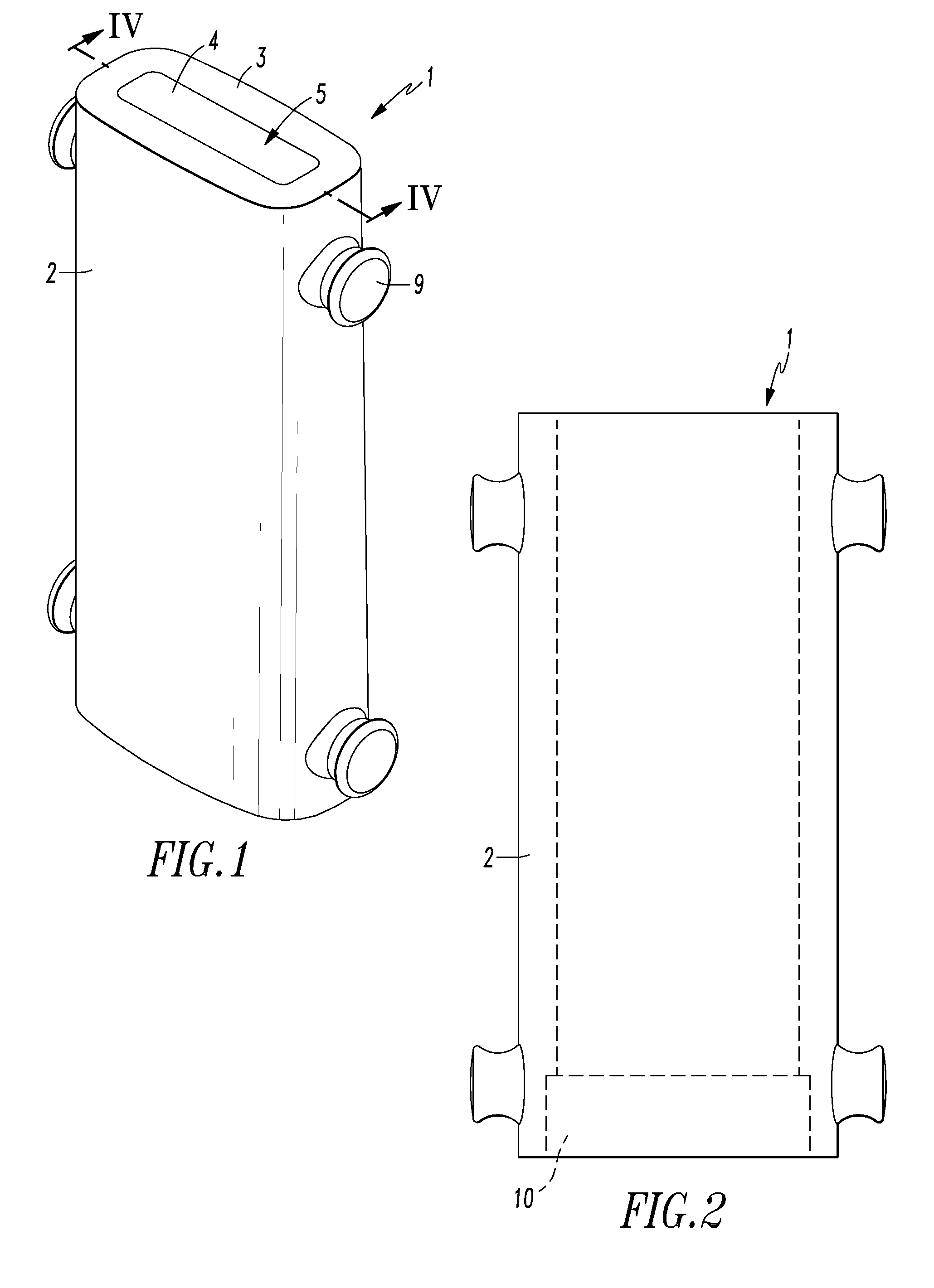
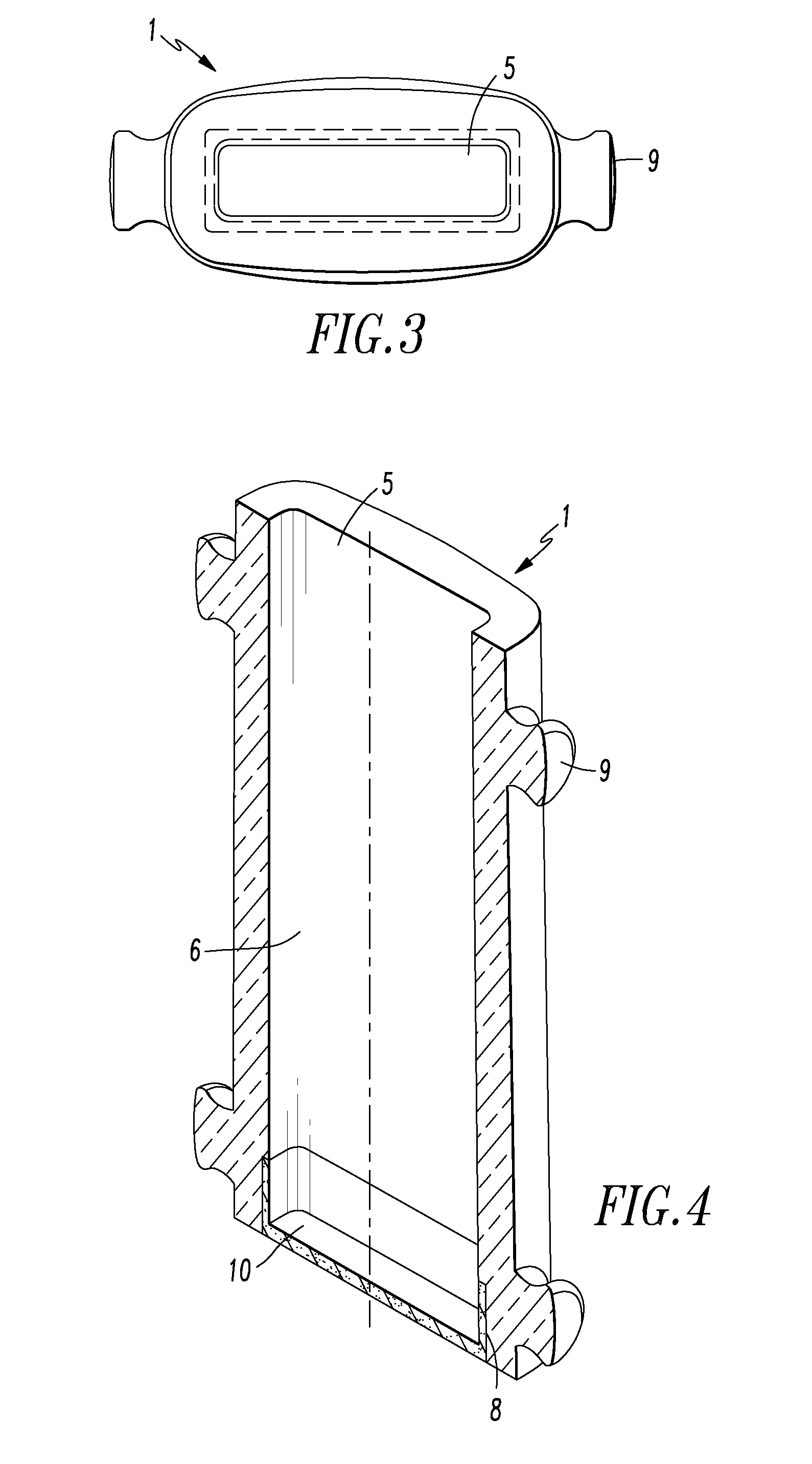
[0024]Referring to FIGS. 1 through 4 I provide an improved mold 1 for casting ingots, electrodes and other metal parts that has a tubular body 2 with an opening 4 in the top 3 of the mold. Handles or lugs 9 are provided on the mold which allowed the mold to be lifted by an overhead crane using hooks that grab the handles. As can be seen most clearly in FIG. 4, I provide a ceramic insert 10 that fits into the bottom of the mold closing off the mold cavity 5. A recess 8 is provided in the cavity wall 6 at the bottom of the mold 1. The recess is sized to receive the side walls 12 and end walls 13 of the ceramic insert 10 shown in FIGS. 5 through 8. A bonding material is applied to the ceramic insert before it is placed within the recess to hold the ceramic insert in the mold. A bonding material sold under the trade name Ladle Lock by Reico Products, Inc. is suitable for this purpose. The binding material is applied to at least a portion of the sidewalls of the ceramic insert before the...


PUM

PropertyMeasurementUnit
heightaaaaaaaaaa
temperaturesaaaaaaaaaa
temperatureaaaaaaaaaa

Abstract

An ingot mold has a body having an open top, a bottom with an opening, and a longitudinal cavity passing through the body. The cavity is defined by a cavity wall extending from the top to the bottom. The cavity wall has a recess adjacent the opening in the bottom of the body. A ceramic insert is positioned within the cavity such that the sidewalls of the ceramic insert are in The recess in the cavity wall.

Description

FIELD OF INVENTION[0001]The invention relates to molds used for metal casting such as cast iron molds into which hot metal is poured and allowed to cool to form an ingot or electrode.BACKGROUND OF THE INVENTION[0002]Many metal alloys are made by mixing raw metals in selected proportions in a furnace and heating the mixture at a desired temperature for a selected time to melt the metals. In many processes the molten metal is taken from the furnace in ladles. Other additives may be added to the molten metal while the melt is in the ladle. Then the metal is poured from the ladle into molds. These molds are often made of cast iron or another metal having a higher melting point than the metal being melted. Those temperatures are often in the range of 2750° F. to 2800° F. (1510° C. to 1538° C.). The molten metal solidifies in the mold to form an ingot, electrode or other metal product. The metal product is removed from the mold for further processing. The mold is cleaned and then reused t...

Claims


Application Information

Patent Timeline
Patent Type & Authority Applications(United States)
IPC IPC(8): B22C9/00B22D29/00
CPCB22C9/00B22D7/06B22D7/068
Inventor FOSTER, RICHARD ALLEN
Owner HAYNES INTERNATIONAL
Why Eureka
Try Eureka