

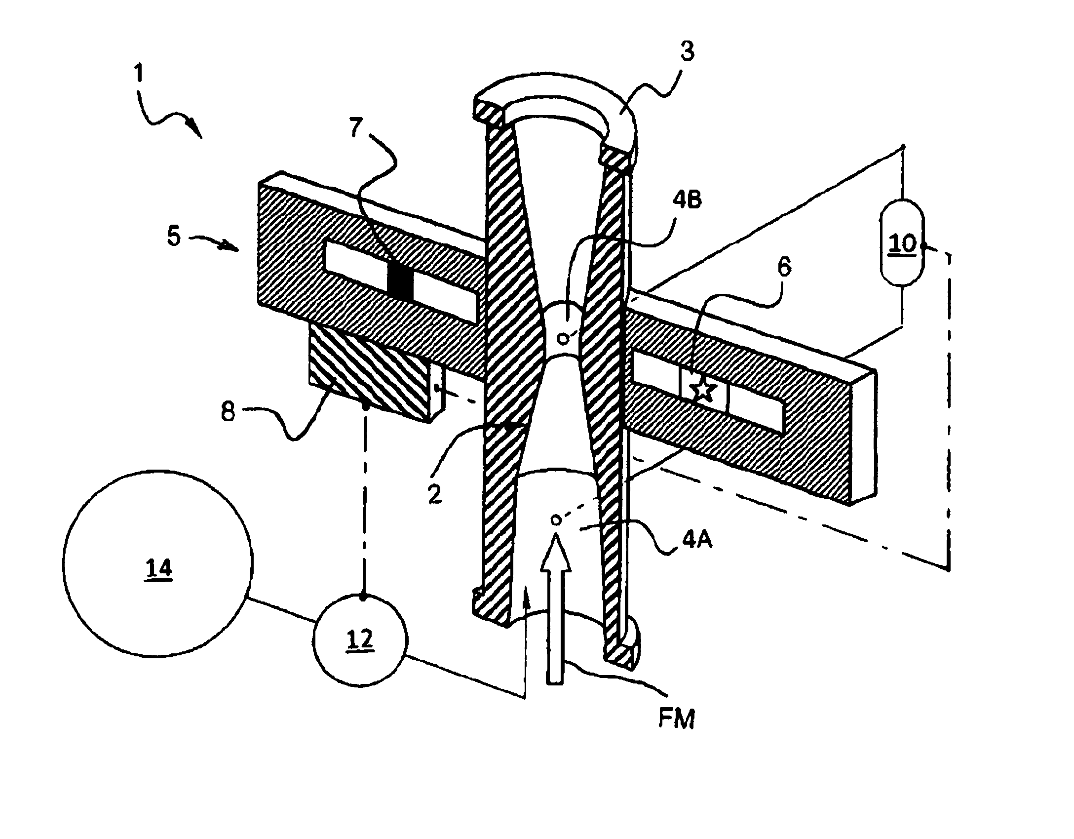
Flow meter system and method for measuring an amount of liquid in a largely gaseous multiphase flow
a multi-phase flow and flow meter technology, applied in the direction of liquid/fluent solid measurement, volume/mass flow by differential pressure, instruments, etc., can solve the problems of gas quality, waste of resources, and loss of accuracy of current multi-phase flow meters in the measurement of liquid fractions, etc., to achieve accurate measurement of minority phases, effective use of flow meter, and large increase in liquid flow
- Summary
- Abstract
- Description
- Claims
- Application Information
AI Technical Summary
Benefits of technology
Problems solved by technology
Method used
Image

Examples
Embodiment Construction
[0024]Various embodiments and aspects of the invention will now be described in detail with reference to the accompanying figures. The terminology and phraseology used herein is solely used for descriptive purposes and should not be construed as limiting in scope. Language such as “including,”“comprising,”“having,”“containing,” or “involving,” and variations thereof, is intended to be broad and encompass the subject matter listed thereafter, equivalents, and additional subject matter not recited. Throughout this application, the subscript “LC,” associated with some parameters, means at line conditions.
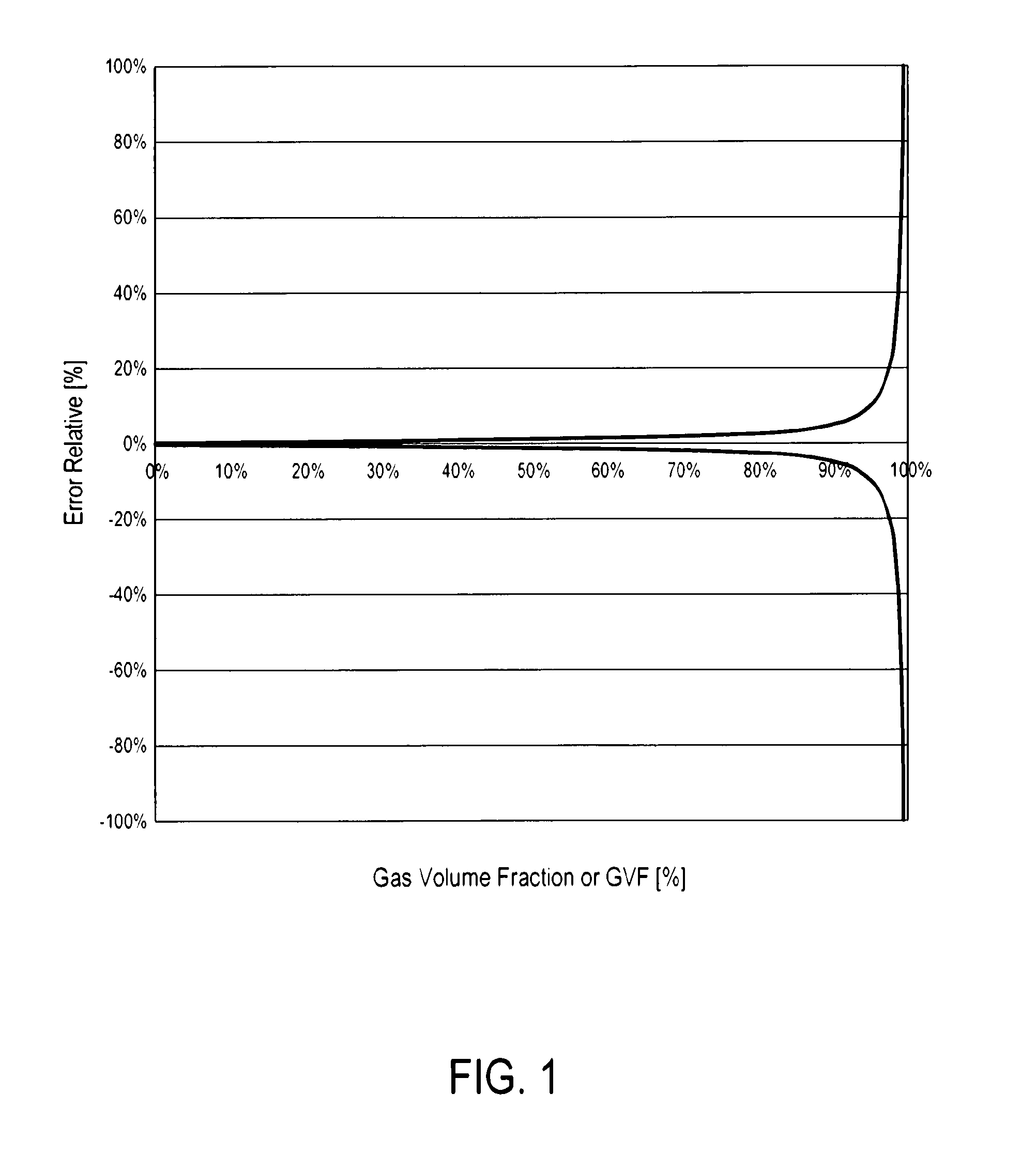
[0025]The trumpet shape of the relative error of the liquid (or oil or water) phase shown in FIG. 1 comes from the mathematical solution or propagation error. The error is substantially independent of the technology used (i.e., technique of measurement). A multiphase flow meter gives a primary output, which is the total volumetric flow rate or mass flow rate. This is less cumbersome to...
PUM
 Abstract
Description
Claims
Application Information