
Multi-Layer Finite Element Method for Modeling of Package Power and Ground Planes

a technology of finite element and package power, applied in the field of system for modeling ground plains, can solve problems such as significant electromagnetic interference (emi), signal integrity (si), and reduce the effective inductance of the plan

Active Publication Date: 2010-08-26
GEORGIA TECH RES CORP
View PDF14 Cites 21 Cited by
  • Summary
  • Abstract
  • Description
  • Claims
  • Application Information

AI Technical Summary

Problems solved by technology

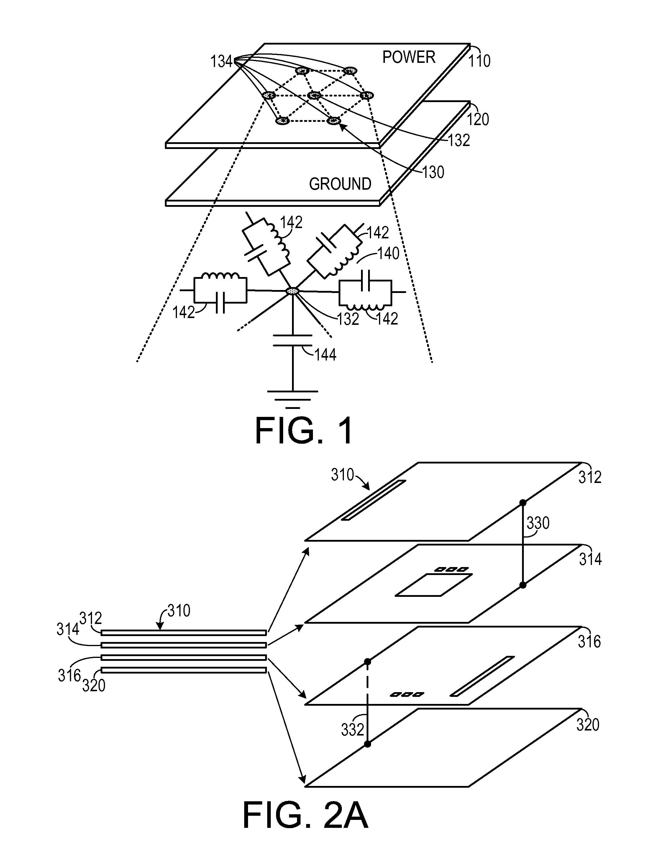
Power and ground planes in electronic packaging can be a major factor for noise coupling.
Excessive supply voltage fluctuations cause signal integrity (SI) problems.
In addition, noise voltage that gets coupled to the edge of the board may cause significant electromagnetic interference (EMI).
In reality, however, planes at the same dc level have to be connected with vias to each other in order to reduce the effective inductance of the planes.
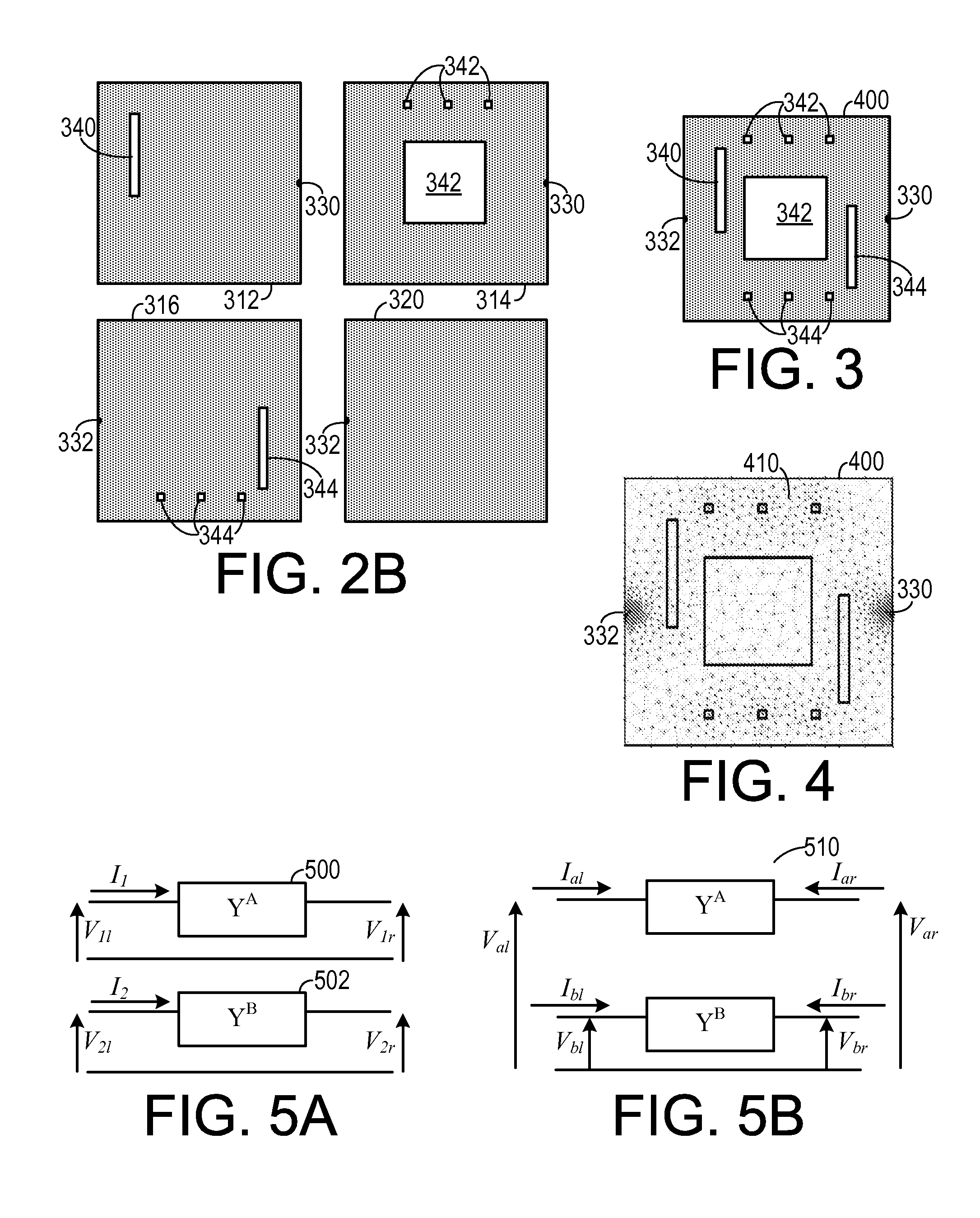
The limitation of the method is that it uses a rigid, square, grid.
To capture very fine structures, the regular mesh becomes dense locally and globally, resulting in a large number of unknowns.
Although M-FDM has been demonstrated in its current implementation for a maximum of 1 million unknowns, this only allows for the modeling of four plane-pairs.
Given that the feature size on package and board are shrinking to allow for greater wiring density, the mesh is a serious limitation of M-FDM.

Method used


Image

  • Multi-Layer Finite Element Method for Modeling of Package Power and Ground Planes
  • Multi-Layer Finite Element Method for Modeling of Package Power and Ground Planes
  • Multi-Layer Finite Element Method for Modeling of Package Power and Ground Planes

Examples


Embodiment Construction

[0025]A preferred embodiment of the invention is now described in detail. Referring to the drawings, like numbers indicate like parts throughout the views. Unless otherwise specifically indicated in the disclosure that follows, the drawings are not necessarily drawn to scale. As used in the description herein and throughout the claims, the following terms take the meanings explicitly associated herein, unless the context clearly dictates otherwise: the meaning of “a,”“an,” and “the” includes plural reference, the meaning of “in” includes “in” and “on.”

[0026]U.S. patent application Ser. No. 11 / 888,705, filed on Aug. 2, 2007 by Engin et al. discloses multilayered finite difference methods for electrical modeling of packages and printed circuit board and is, therefore, incorporated herein by reference. U.S. patent application Ser. No. 12 / 288,616, filed on Oct. 22, 2008 by Han et al. discloses modeling electrical interconnections in three-dimensional structures and is, therefore, incorp...


PUM


Abstract

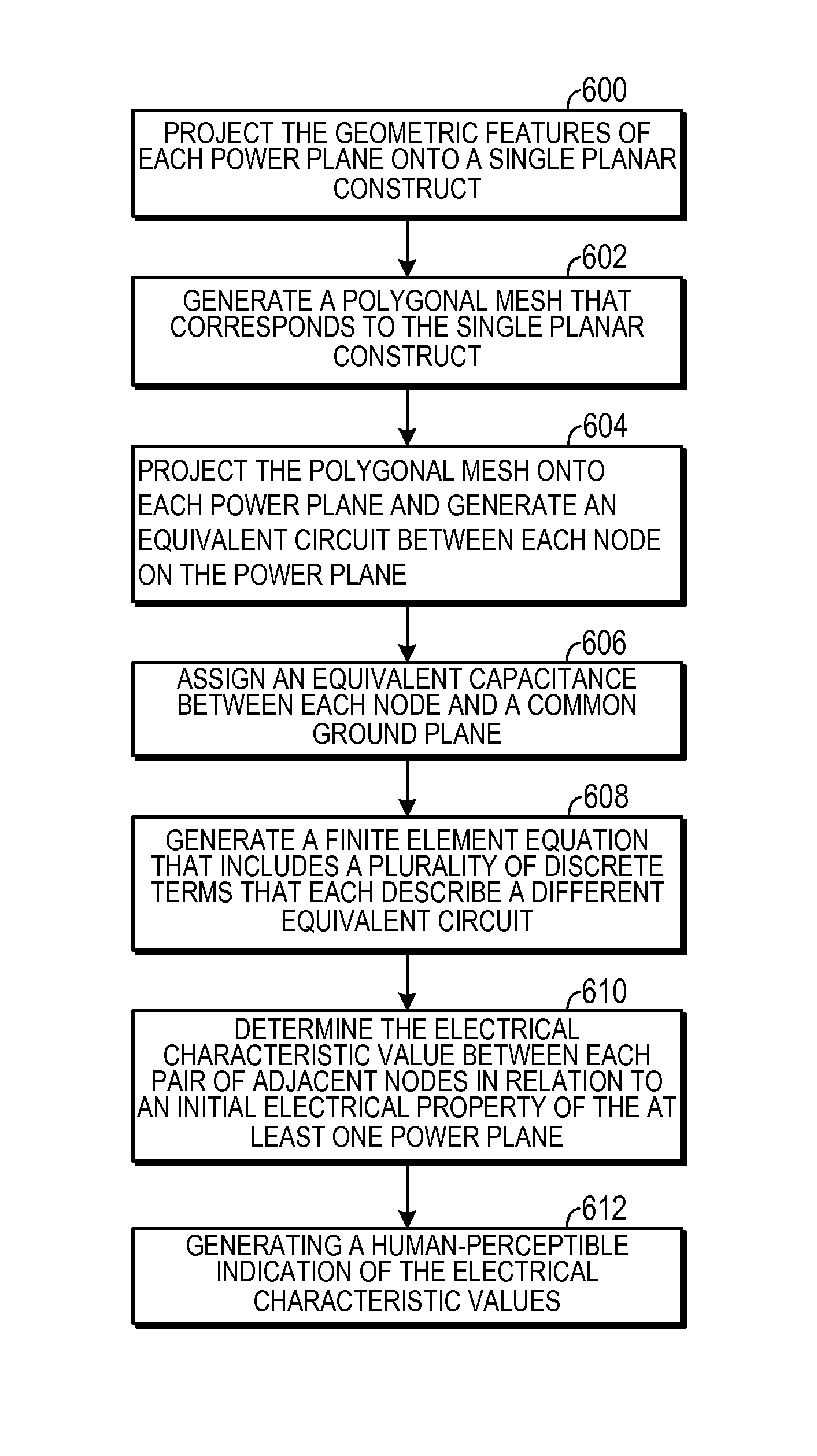
In a method for simulating electrical characteristics of a plurality of power planes, each power plane includes a plurality of geometric features. The geometric features of each power plane are projected onto a single planar construct. A polygonal mesh, including a plurality of pairs of interconnected nodes, that corresponds to the single planar construct is generated. The polygonal mesh is projected onto at least one power plane an equivalent circuit between each adjacent node of the plurality of interconnected nodes is projected onto the power plane. An equivalent capacitance is assigned between each node and a common ground planer. A finite element equation that includes a plurality of discrete terms is generated. The equation is solved, thereby determining the electrical characteristic value between each pair of adjacent nodes.

Description

CROSS-REFERENCE TO RELATED APPLICATION(S)[0001]This application claims the benefit of U.S. Provisional Patent Application Ser. No. 61 / 154,543, filed Feb. 23, 2009, the entirety of which is hereby incorporated herein by reference.BACKGROUND OF THE INVENTION[0002]1. Field of the Invention[0003]The present invention relates to electronic device modeling systems and, more specifically, to a system for modeling ground plains used in circuit boards.[0004]2. Description of the Related Art[0005]A high-performance digital or mixed signal system can contain thousands of signal lines that must be routed on several layers in the package and printed circuit board (PCB). These signal layers must be placed between or over power and ground planes in order to have an impedance controlled board including microstrip or stripline transmission lines. A power or ground plane also prevents any coupling of signal lines in an upper layer to signal lines in a lower layer. As a result of this, many power and ...

Claims


Application Information

Patent Timeline
IPC IPC(8): G06F17/50
CPCG06F17/5018G06F2217/40G06F17/5036G06F30/367G06F30/23G06F2113/18
Inventor BHARATH, KRISHNASWAMINATHAN, MADHAVAN
Owner GEORGIA TECH RES CORP
Learn More