Load Driving Device, and Lighting Apparatus and Liquid Crystal Display Device Using the Same
a technology of driving device and load, which is applied in the direction of electric variable regulation, process and machine control, instruments, etc., can solve the disadvantages of the overall efficiency of the electronic device that includes a power supply circuit and a load, increase energy loss, and require additional space and cost for the power supply circuit and load
- Summary
- Abstract
- Description
- Claims
- Application Information
AI Technical Summary
Benefits of technology
Problems solved by technology
Method used
Image
Examples
tenth embodiment
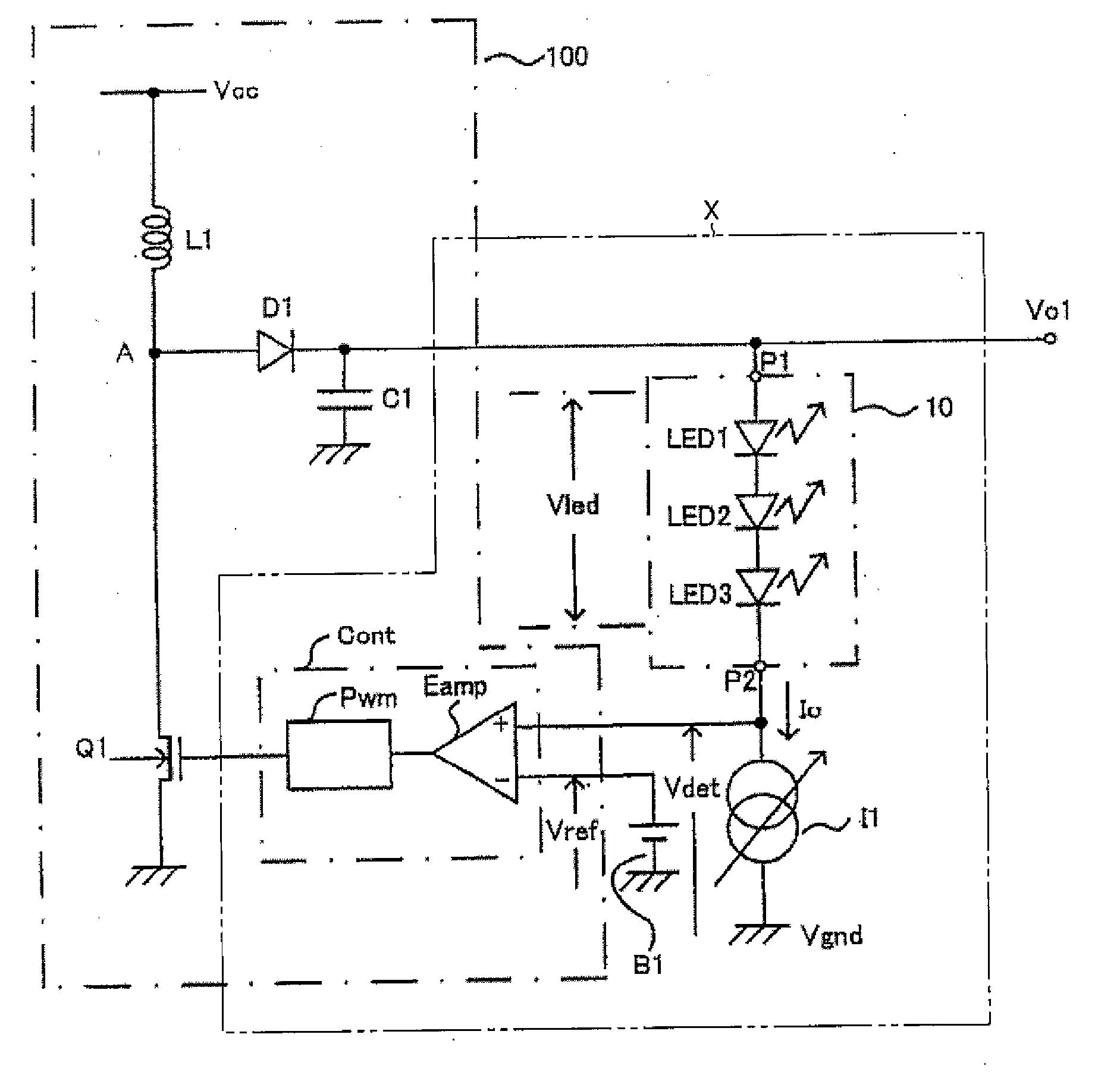
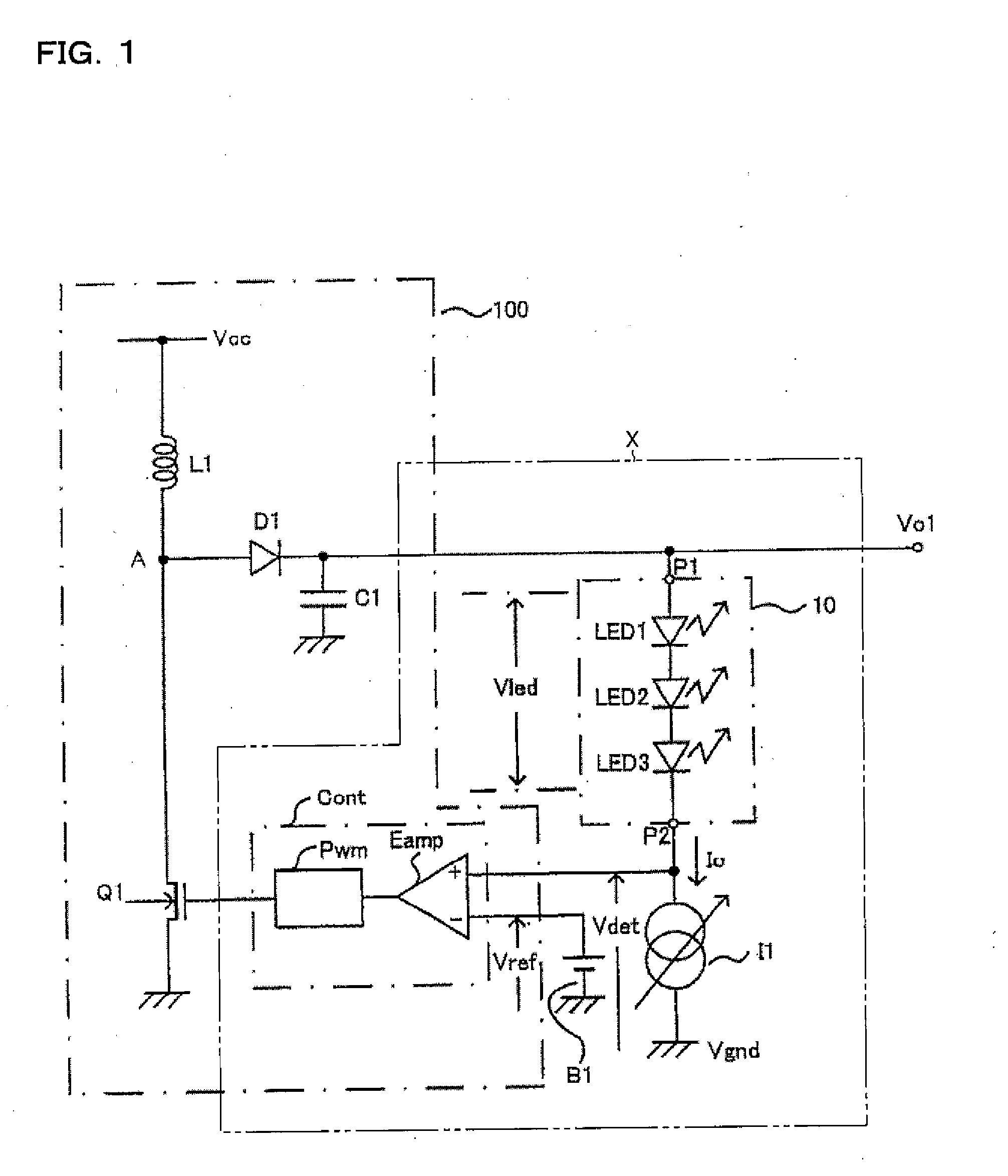
[0172]FIG. 14 is a view showing a configuration of a load driving device in accordance with a tenth embodiment of the present invention. The load driving device of the tenth embodiment is characterized in that external loads 10 and 20 of multiple systems are connected, that as constant-current sources I10 and I20, an internal configuration different from FIG. 3 (a configuration similar to the ninth embodiment) is adopted and positions from which detection voltages Vdet1 and Vdet2 are derived have been changed, that a selector SLT for selecting any one of the detection voltages Vdet1 and Vdet2 (one at a lower voltage level) and outputting it to an error amplifier Eamp is provided, that the error amplifier Eamp has input terminals of two systems (a noninverting input terminal (+) and an inverting input terminal (−)), and that output feedback circuits (error amplifiers EA10 and EA20, and reference voltage sources B10 and B20) for controlling continuity level of transistors Q21 and Q22 ...
eleventh embodiment
[0173]FIG. 15 is a view showing a configuration of a load driving device in accordance with an eleventh embodiment of the present invention. The load driving device of the eleventh embodiment is characterized in that external loads 10 and 20 of multiple systems are connected, that as constant-current sources I10 and I20, an internal configuration different from FIG. 3 (a configuration similar to the ninth embodiment) is adopted and positions from which detection voltages Vdet1 and Vdet2 are derived have been changed, that a selector SLT for selecting any one of the detection voltages Vdet1 and Vdet2 (one at a lower voltage level) and outputting it to an error amplifier Eamp is provided, and that the error amplifier Eamp has input terminals of two systems (a noninverting input terminal (+) and an inverting input terminal (−)).
twelfth embodiment
[0174]FIG. 16 is a view showing a configuration of a load driving device in accordance with a twelfth embodiment of the present invention. The load driving device of the twelfth embodiment is characterized in that external loads 10 and 20 of multiple systems are connected, that resistances R10 and R20 for current detection are provided at positions of constant-current sources I10 and I20 and detection voltages Vdet1 and Vdet2 are derived from one end of each, that a selector SLT for selecting any one of the detection voltages Vdet1 and Vdet2 (one at a lower voltage level) and outputting it to an error amplifier Eamp is provided, that the error amplifier Eamp has input terminals of two systems (a noninverting input terminal (+) and an inverting input terminal (−)), and that output feedback circuits (an error amplifier EA, a reference voltage source B2, and resistances R2 and R3) for controlling continuity level of transistors Q21 and Q22 placed respectively between the external loads...
PUM
 Abstract
Description
Claims
Application Information
 - R&D
- Intellectual Property
- Life Sciences
- Materials
- Tech Scout
- Unparalleled Data Quality
- Higher Quality Content
- 60% Fewer Hallucinations
Browse by: Latest US Patents, China's latest patents, Technical Efficacy Thesaurus, Application Domain, Technology Topic, Popular Technical Reports.
© 2025 PatSnap. All rights reserved.Legal|Privacy policy|Modern Slavery Act Transparency Statement|Sitemap|About US| Contact US: help@patsnap.com


