Array speaker system and array microphone system

Inactive Publication Date: 2010-09-02
YAMAHA CORP
View PDF21 Cites 24 Cited by
  • Summary
  • Abstract
  • Description
  • Claims
  • Application Information

AI Technical Summary

Benefits of technology

[0042]In the present invention, the linked mode and the position therein are detected, and the delay quantity of each microphone unit is set according to its position. As a result, the directional characteristics of the entire array mic

Problems solved by technology

A surround system realized by multiple speakers in this way, however, required complex wiring systems to each speaker, and also had the problem that space was required to install multiple speakers.
If the speaker unit spacing d is increased, however, the problem of audio beam generated in a direction other than the target direction may occur because of the spatial alias, so direction control in the high frequency band becomes difficult.
Playback of bandwidth used for telephone voice was possible, but playback of bandwidth required for home theaters (for example, 250 Hz to 12 kHz approximately) could not be realized.
To realize this, the number of speaker units needs to be increased, but the problem that arises is that cost increases when the number of speaker un

Method used


Image

  • Array speaker system and array microphone system
  • Array speaker system and array microphone system
  • Array speaker system and array microphone system

Examples


Example

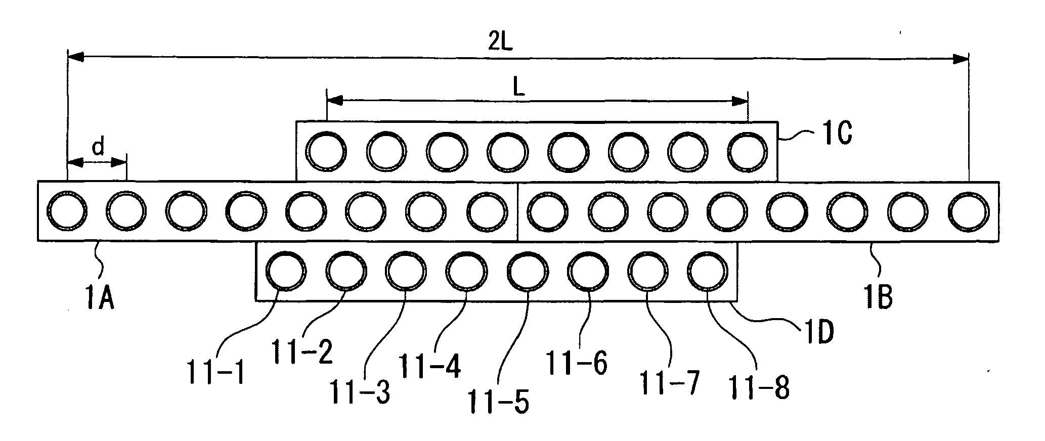
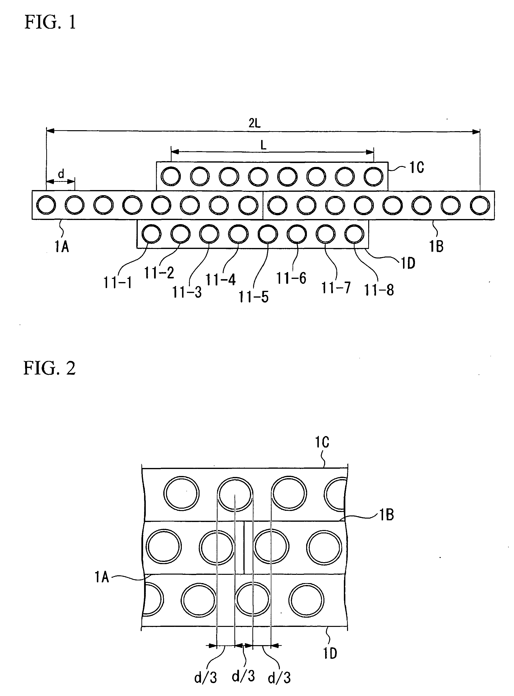
[0066]FIG. 1 is a schematic view showing the configuration of an array speaker system related to the embodiments of the present invention. As shown in this figure, this array speaker system is provided with a plurality of speakers 1A to 1D.

[0067]Speaker 1A and speaker 1B are aligned and linked in the left-right direction. Speaker 1C is linked to the upper part of speaker 1A and speaker 1B; speaker 1D is linked to the lower part of speaker 1A and speaker 1B.

[0068]Each speaker 1 is configured with 8 speaker units 11-1 to 11-8 disposed in a line at spacing d, and is equivalent to the line array unit of the present invention. The speaker unit used is generally a cone-shaped speaker unit, but other shapes, such as horn-shaped speaker units may also be used. The distance between one end of the speaker unit 11-1 and the other end of the speaker unit 11-8 is L. This distance L is taken as the width L of the speaker 1. The array speaker system of the present embodiment has the speaker 1A and...


PUM


Abstract

A plurality of speakers are linked in the present invention. The linked position of each speaker can be detected. Audio signal is input to any one of the master speakers. The master speaker synchronizes the other linked speakers, and supplies audio signals to other speakers. It also controls the delay quantity of the speaker unit of each speaker. For a single speaker, the apparent width of this array speaker system becomes twice the width, and the speaker unit spacing becomes one third the spacing. Consequently, the frequency band at which direction is controllable becomes enhanced.
Additionally, a plurality of microphone devices are linked at the top, bottom, left and right sides in the present invention. The linked position of each microphone device can be detected. Audio data is output from each microphone device to the master microphone device. The master microphone device synchronizes with other linked microphone devices, treats them as array microphones in the entire linked array microphone system, and controls the delay quantity of the microphone unit of the microphone device. For a single microphone device, the apparent width of this array microphone system becomes twice the width, and the microphone unit spacing becomes one-third the spacing. Consequently, the frequency band at which direction is controllable becomes enhanced.

Description

TECHNICAL FIELD[0001]The present invention relates to direction controllable array speaker system, particularly to array speaker system with enhanced direction controllable frequency band. Additionally, the present invention relates to direction controllable array microphone system, particularly to array microphone system with enhanced direction controllable frequency band.[0002]Priority is claimed on Japanese Patent Application No. 2005-205923, filed Jul. 14, 2005, and the Japanese Patent Application No. 2005-208321, filed Jul. 19, 2005, both filed with the Japanese Patent Office, the contents of which are incorporated herein by reference.BACKGROUND ART[0003]In recent years, home theaters where one can enjoy a highly realistic feeling of a movie theater within the home, are becoming popular. A home theater with multiple speakers installed to surround the listener as represented by a 5.1-channel surround is common. A surround system realized by multiple speakers in this way, however...

Claims


Application Information

Patent Timeline
IPC IPC(8): H04R25/00
CPCH04R1/403H04R1/406H04R2201/403H04R2201/401H04R3/12
Inventor ISHIBASHI, TOSHIAKITAMARU, TAKUYA
Owner YAMAHA CORP
Why Eureka
Try Eureka