Variable Displacement Variable Pressure Vane Pump System

a variable pressure vane and pump system technology, applied in the direction of machines/engines, positive displacement liquid engines, liquid fuel engines, etc., can solve the problems of nonlinear variation in the output of the pump and the variation of the lubrication requirements of the mechanical system, significant energy loss, and significant energy loss, and achieve the effect of granularity

Active Publication Date: 2010-09-02
HANON SYST EFP CANADA LTD
View PDF21 Cites 36 Cited by
  • Summary
  • Abstract
  • Description
  • Claims
  • Application Information

AI Technical Summary

Benefits of technology

[0008]The present invention provides a variable displacement variable pressure vane pump system for providing lubrication oil to mechanical systems such as internal combustion engines and/or automatic transmissions. The system includes at least a first control mechanism, which can be a control chamber directly acting on the control slider or a control chamber and control cylinder which acts on the control slider and a second control mechanism which is a control chamber and control cylinder which acts on the control slider. A control valve, operated by an engine control unit or other suitable control mechanism, can selectively vary pressurized lubrication oil to the second control mechanism to allow the output of the pump system to mo

Problems solved by technology

While the lubrication requirements of the mechanical system also vary with the operating speed of the mechanical system, unfortunately the variation in the output of the pump and the variation of the lubrication requirements of the mechanical system are generally nonlinear.
In some operating conditions such as low oil temperatures, the overproduction of pressurized lubricating oil can be 500% of the mechanical system's needs so, while such systems work reasonably well, they do result in a significant energy loss a

Method used


Image

  • Variable Displacement Variable Pressure Vane Pump System
  • Variable Displacement Variable Pressure Vane Pump System
  • Variable Displacement Variable Pressure Vane Pump System

Examples


Embodiment Construction

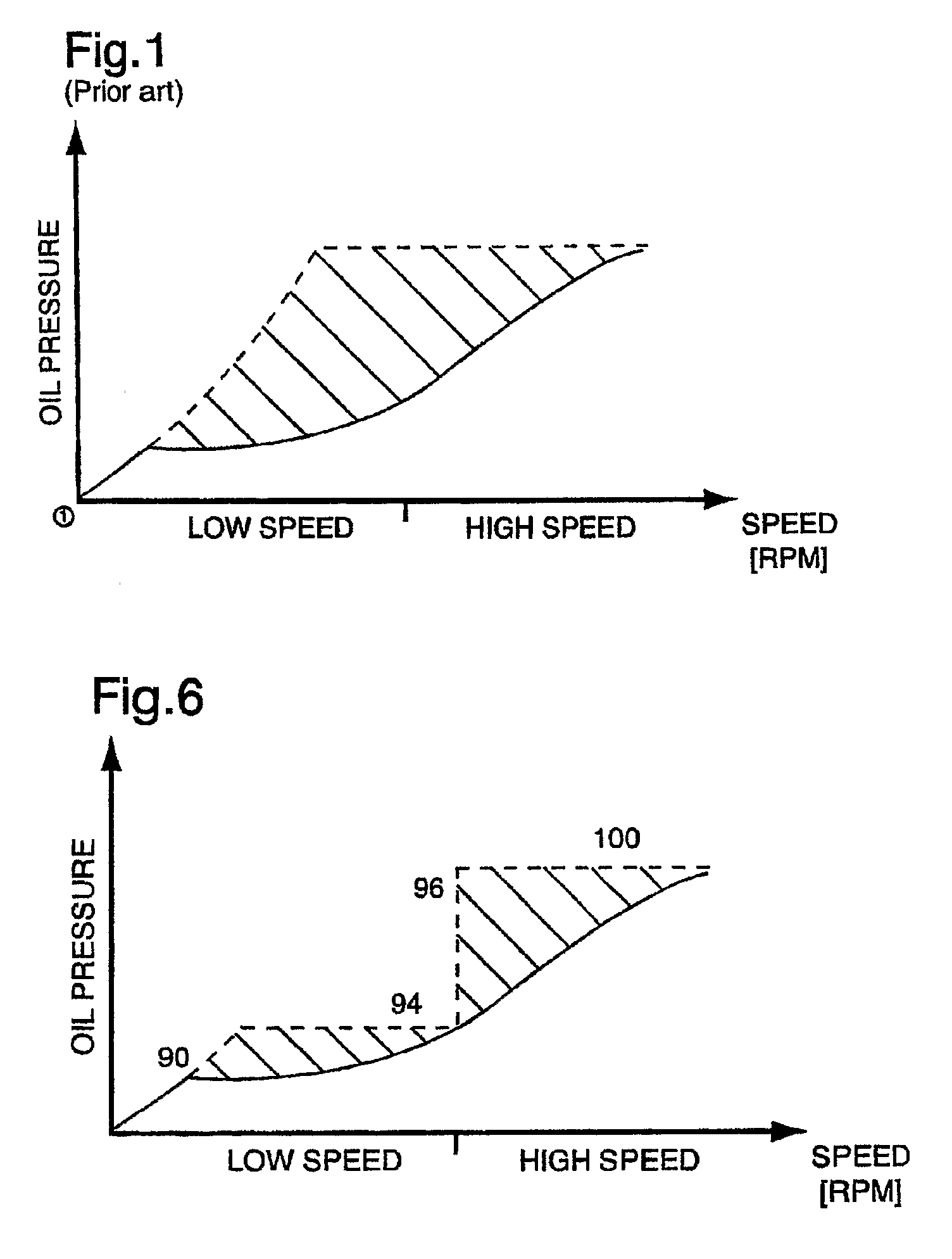
[0023]FIG. 1 shows a typical plot of the lubricating oil pressure requirement (shown in solid line) of a mechanical system, such as a typical internal combustion engine, versus the output (shown in dashed line) of a prior art variable displacement pump, such as the pump taught in the above-mentioned Schuster patent. The corner on the output (dashed line) results from the movement of the control slide by the control piston to reduce the displacement of the pump as the output of the pump reaches a preset value. The shaded area between the engine demand curve and the pump output curve represents the engine operating conditions wherein energy is lost as the pump pressure output exceeds engine demand.

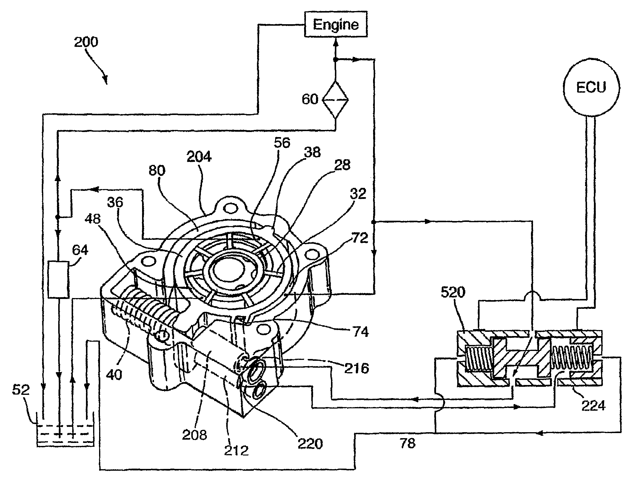
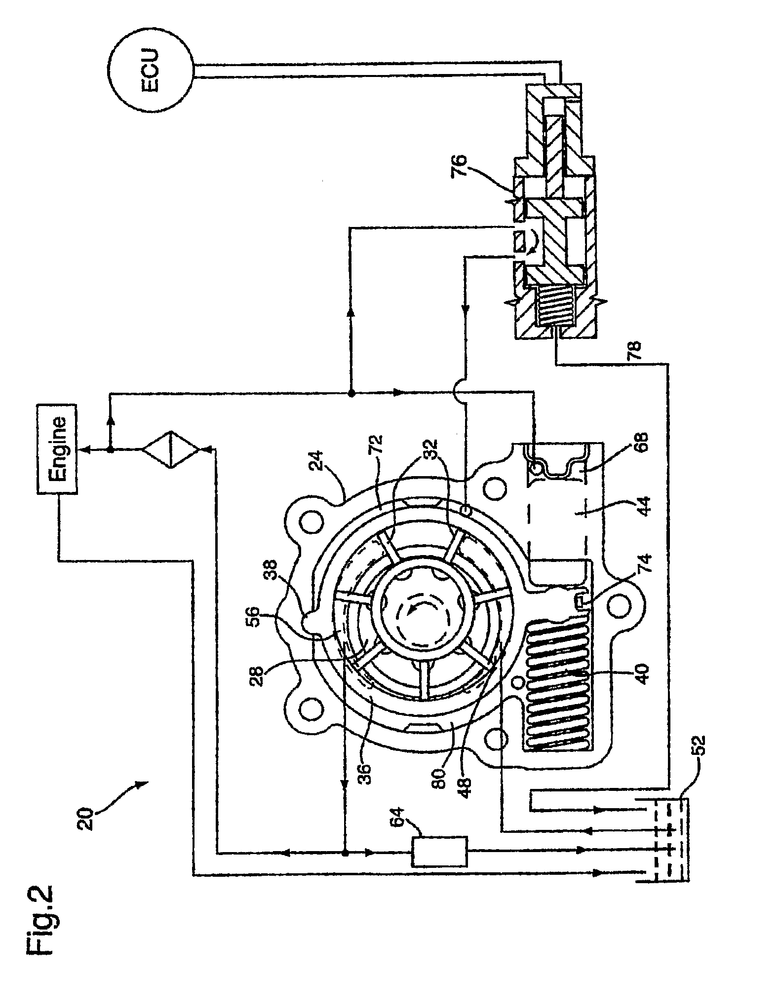
[0024]A lubrication pump system in accordance with the present invention is indicated generally at 20 in FIG. 2. While in the following discussion the lubrication needs of an internal combustion engine are discussed, the present invention is not so limited and the present invention can be ad...


PUM


Abstract

A traditional variable displacement vane pump must be designed to provide maximum fluid pressure and thus experiences reduced energy efficiency when the system operating conditions do not necessitate such high requirements. A variable displacement variable pressure vane pump system is provided comprising a first control mechanism, which can be a control chamber (68) directly acting on the control slider (36) or a control chamber (68) and control cylinder (44) which acts on the control slider (36) and a second control mechanism which is a control chamber (72) and control cylinder (44) which acts on the control slider (36). A control valve (76), operated by an engine control unit or other suitable control mechanism, selectively provides pressurized lubrication oil to the second control mechanism to allow the output of the pump system to more closely match the requirements of the mechanical system.

Description

FIELD OF THE INVENTION[0001]The present invention relates to variable displacement vane pumps. More specifically, the present invention relates to a variable displacement variable pressure vane pump system for mechanical systems such as internal combustion engines or automatic transmissions.BACKGROUND OF THE INVENTION[0002]Mechanical systems such as internal combustion engines and automatic transmissions typically include a lubrication pump to provide lubricating oil, under pressure, to many of the moving components and / or subsystems of the mechanical systems. In most cases, the lubrication pump is driven by a mechanical linkage to the mechanical system and thus the operating speed, and output, of the pump varies with the operating speed of the mechanical system. While the lubrication requirements of the mechanical system also vary with the operating speed of the mechanical system, unfortunately the variation in the output of the pump and the variation of the lubrication requirement...

Claims


Application Information

Patent Timeline
IPC IPC(8): F04B49/00
CPCF04C14/226F01M1/02F16N13/20F04C2/04F01M2001/0238F04C14/22F04C14/24F04C15/06
Inventor TANASUCA, CEZARSHULVER, DAVID R.
Owner HANON SYST EFP CANADA LTD
Why Eureka
Try Eureka