Eureka AIR delivers breakthrough ideas for toughest innovation challenges, trusted by R&D personnel around the world.

Device amd method for teaching work delivery position to robot

a technology of robots and devices, applied in the field of apparatus and methods for teaching workpiece transfer positions to robots, can solve the problems of consuming a lot of time, imposing stress, and risk of wafer breakage, and achieve the effects of inexpensive teaching, short teaching time, and easy maintenan

Inactive Publication Date: 2010-09-02
HIRATA & CO LTD
View PDF5 Cites 4 Cited by
  • Summary
  • Abstract
  • Description
  • Claims
  • Application Information

AI Technical Summary

Benefits of technology

[0014]As mentioned above, the apparatus for teaching a workpiece transfer position to a robot of the present invention comprises the first jig, the second jig, and the teaching means for teaching the control unit of the robot a position of the robot hand at the time when the position of the center of the workpiece indicated by the first jig is aligned with the position of the center of the workpiece indicated by the second jig. Therefore, the present invention can provide an apparatus for teaching a workpiece transfer position to a robot which can implement inexpensive teaching without use of a sensor, an image pickup means, or the like and can carry out teaching in a short time.
[0015]Also, use of the apparatus can provide a method for teaching a workpiece transfer position to a robot which can implement inexpensive teaching and can carry out teaching in a short time.

Problems solved by technology

In transfer of a circular substrate; for example, a wafer, between apparatuses each having a holding means of a so-called edge clamp type for fixedly holding the wafer at the circumference, center misalignment of the wafer causes imposition of stress on the wafer from a holding portion of the holding means, involving the risk of breakage of the wafer.
Therefore, teaching consumes much time, and teaching apparatuses become expensive.

Method used


Image

  • Device amd method for teaching work delivery position to robot
  • Device amd method for teaching work delivery position to robot
  • Device amd method for teaching work delivery position to robot

Examples


embodiment

[0029]Next, an embodiment of the present invention will be described.

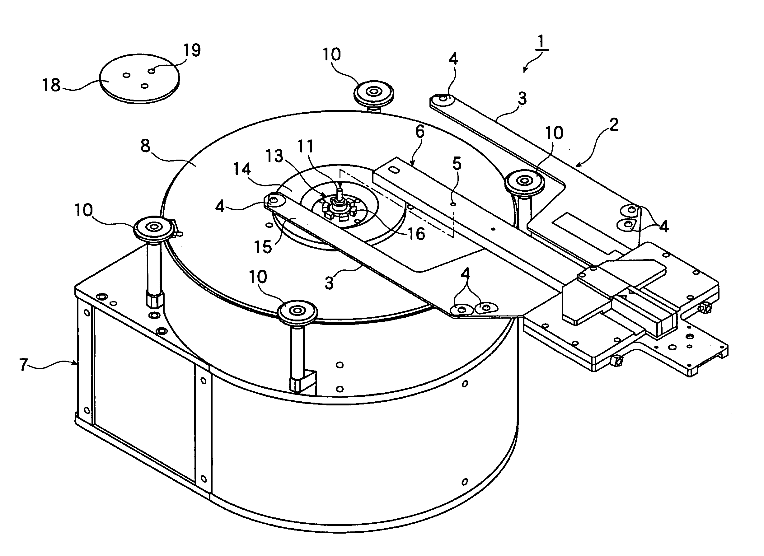
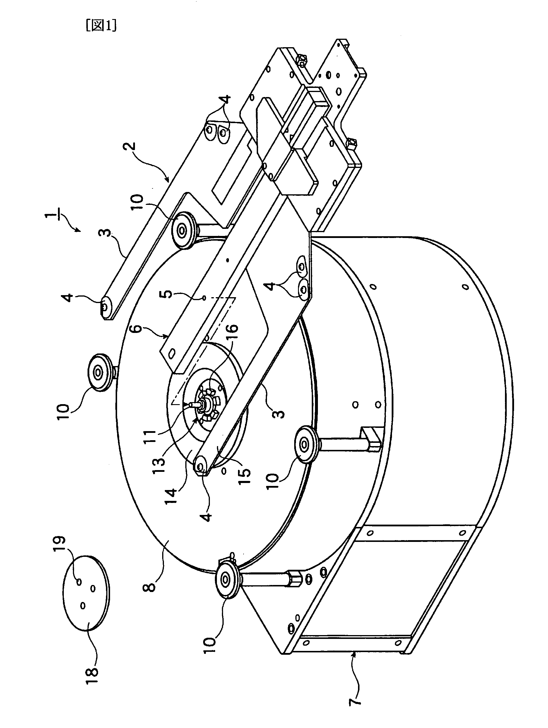
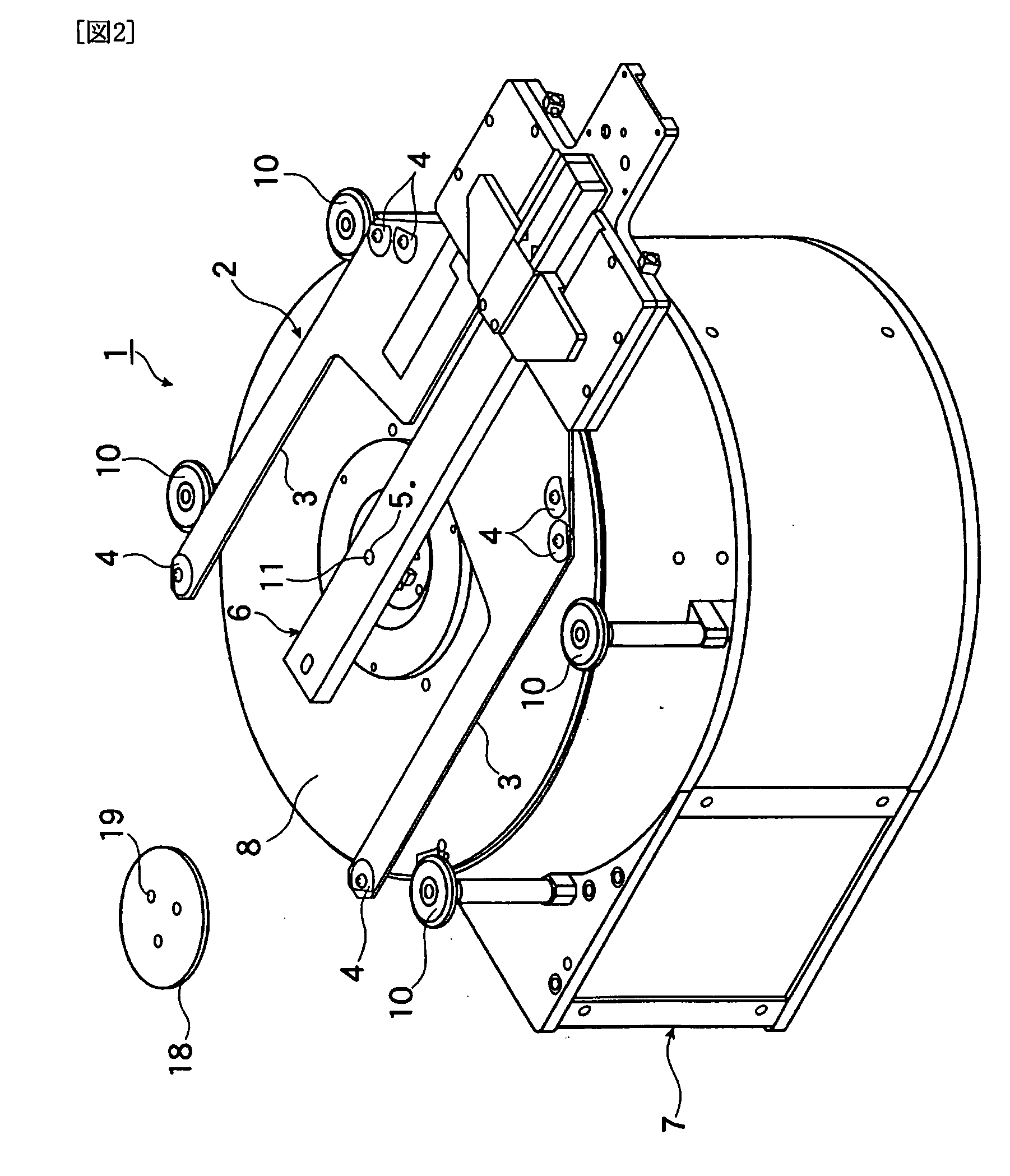
[0030]FIG. 1 is a perspective view of an apparatus for teaching a workpiece transfer position to a robot of the present embodiment. FIG. 2 is a perspective view showing a state in which the teaching apparatus carries out teaching.

[0031]The apparatus for teaching a workpiece transfer position to a robot of the present embodiment is used in, for example, a semiconductor manufacturing plant, to teach the robot beforehand a workpiece transfer position at which center misalignment of a workpiece does not occur in transfer of the workpiece between a hand of the robot (robot hand) and a workpiece table provided on a stationary-side apparatus. The stationary-side apparatus mentioned in the present embodiment is a pneumatic levitation aligner, but is not limited thereto. The stationary-side apparatus may be a loader / unloader of a processing apparatus.

[0032]As shown in FIGS. 1 and 2, the apparatus 1 of the present embodiment...


PUM


Abstract

[PROBLEMS] To provide a device and a method for teaching a work delivery position to a robot capable of teaching to the robot at low cost in a short time.[MEANS FOR SOLVING PROBLEMS] This device for teaching the work delivery position to the robot teaches, to the robot beforehand, the work delivery position where the center position of the work is not deviated when the work is delivered between a movable side robot hand (2) and a fixed side work loading table (8). The device comprises a first tool (6) fitted to the robot hand (2) and indicating the center position of the work when a movable side work holding means holds the work a second tool (13) fitted to the work loading table (8) and indicating the center position of the work when a fixed side work holding means holds the work on the work loading table (8), and a teaching means teaching, to a robot controller, the position of the robot hand (2) when the center position of the work indicated by the first tool (6) is aligned with the center position of the work indicated by the second tool (13).

Description

TECHNICAL FIELD[0001]The present invention relates to an apparatus and method for teaching a workpiece transfer position to a robot, used to teach the robot beforehand a workpiece transfer position at which center misalignment of the workpiece does not occur in transfer of the workpiece between apparatuses each having a workpiece-holding means for holding the workpiece at the circumference, and particularly to such an apparatus and method which can implement inexpensive teaching and can carry out teaching in a short time.BACKGROUND ART[0002]In transfer of a circular substrate; for example, a wafer, between apparatuses each having a holding means of a so-called edge clamp type for fixedly holding the wafer at the circumference, center misalignment of the wafer causes imposition of stress on the wafer from a holding portion of the holding means, involving the risk of breakage of the wafer. Therefore, in order to prevent center misalignment of a wafer in such transfer of the wafer, a c...

Claims


Application Information

Patent Timeline
Patent Type & Authority Applications(United States)
IPC IPC(8): G06F19/00
CPCG05B19/421G05B2219/39021H01L21/68707G05B2219/50125H01L21/682G05B2219/50036
Inventor MATSUMURA, KAZUYUKI
Owner HIRATA & CO LTD
Why Eureka
Eureka Blog
Learn More